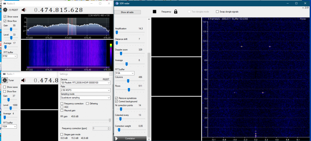
Passive radars are known already from WW2. Here I present my solution to use RTL-SDR dongle and fast Radeon video card (NVIDIA is also possible but the library are different). This software uses OpenCL libraries from Radeon (similar are also for NVIDIA). Program supports up to 2 coherent receivers but for passive radar one dongle is enough. I would like to thanks Frank from Finland for excellent idea and hard work!
Old x64 version of radar software (AMD OpenCL) may be downloaded from here.
The GitHub code and binaries of Passive Radar for Windows 11 64bit is here.
The code for super fast ambiguity function FAF (NVIDIA CUDA) is here. The library supports one or two dongles (correlated) 🙂

The Passive radar in action
The resolution is 40×40 with around 70 frames/s of continous data flow! The RTL-SDR dongle does not have the best parameters, but analyzing 2097152 bits per frame gives interesitng results. The movie was recorded in a not the best location because the DVB-T transmitter (490MHz) was located on the right at 0.5 km and some buildings close to the road shadowed the signal. Cars give a negative doppler shift as they drive away. Arriving vehicles produce a positive doppler shift. The distance is around 50–300 m. The car’s speed is around 30–50 km/h. Each displayed frame is an average of 30 frames. The background is substracted and the left-right symetric filter is applied (substract the lower value from both pixels on left and right from the main 0 doppler shift line).
The link to the movie is here and here. Another exaple of this passive radar is a a video of the scattered signal from plane around 10km away (below).
PassiveRadar in action. The DVB-t tower is around 20km from my antenna. The DVB-t power is 56kW. The signal comes from a small sport plane (Cesna?) around 6-8 km from my place in the direction of DVB-t. The signal sometimes is below the line of trees because the plane has a low altitude of 1km.
Curently a new version of Radar 300% faster is available in Github. This version works togeter with improved code for Ambiguity function in repository it is AmbiguityUltra. Movie form this version of Radar is here. The interesting part is after one minute.
PassiveRadar settings:
Nr. columns 200
Nr rows ~300
Signal average 40 frames
Static background correction after recording
Doppler zoom ~20
Amplification 2.8
With function remove symmetrices
New passive radar project
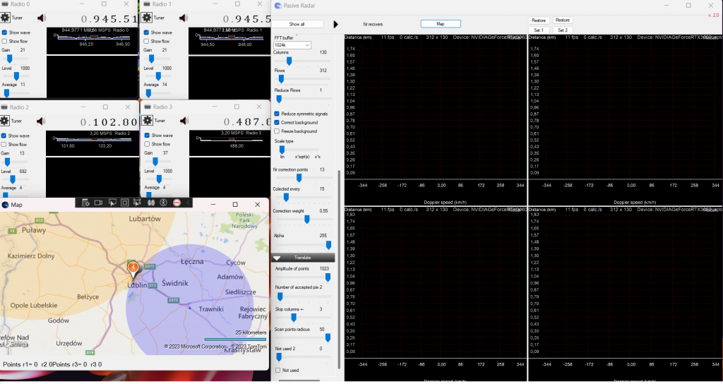
Because the simple radar project works perfectly, I decided to construct real radar connected to Bing maps.
The new project consists of:
1) Radio with 4 passive radars that are tuned to the different DVB-t frequencies. The towers cannot lay on the same line! (this part is already done).

2) Signal translation to a list of time and Doppler shifts In digital form for each radar (a list of data). One bistatic radar can give more than one signal, e.g., other objects. The algorithm searches for blops on the screen (or array) and returns the middle of the blop (in radar as a geometrical center of mass center from the pixel value). The code is here. and the example is below. The red dots are the geometrical centers of the blops. The process is controlled by two arrays that are 'tested’ and 'found’. The heart of the algorithm is:
   for (int i = 0; i < blop_points.Count; i++)
       if (scaned_points[blop_points[i].X, blop_points[i].Y] == false)
           blop_points.AddRange(ScanNeighburst(blop_points[i]));
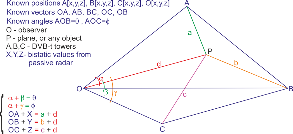
3) Mathematics to calculate the real position of the plane based on the position of 3 DVB-t towers. This is: observer position, 3 bistatic signals and DVB-t positions. It was a good math exercise; see figure below. To get the coordinates of point P(plain) in 3D you have to solve system of the presented equations (in color) with additional 9 pitagoras relations, which are not shown. The result has two solutions but only one with positive height over ground is the most interesting (done).

Below is the code that solves the problem for P. This problem can be reversed. O (observer) can be a position of DVB-t and A,B, C can be a position of observers. The math is exactly the same. With 4 computers connected to 4 different recivers it is possible to get exact position of point P. The smal inconvenience is the analysis of the data which have to be done on one computer or server. To do this every computer has to send its data with time stamp for every calculated frame. This is not that much data. But this seems like ilitary solution. Other option is to use two SVB-t towers with two computers (with recivers). And the work is as above, send calculated frames with time stamps to the server.
        static void CalculateDistance3(double OA, double OB, double OC, double X,
                                       double Y, double Z, ref Data dat)
        {
            //All geometry is in ECI (km)

            double S1, S2, S3, S4, S5, S6, S7, S8, S9, S10, S11, S12;

            S1 = (2.0 * OA * X + X * X);
            S2 = -2.0 * (OA + X);
            S3 = (2.0 * OB * Y + Y * Y);
            S4 = -2.0 * (OB + Y);
            S5 = (2.0 * OC * Z + Z * Z);
            S6 = -2.0 * (OC + Z);

            //Can be calculated once for given BTV positions
            S7 = Math.Cos(dat.teta);
            S8 = Math.Sin(dat.teta);
            S9 = Math.Cos(dat.phi);
            S10 = Math.Sin(dat.phi);

            S11 = OA / OB;
            S12 = OA / OC;

            double P1, P2, P3, P4;

            P1 = S11 / S8;
            P2 = S7 / S8;
            P3 = S12 / S10;
            P4 = S9 / S10;

            double P = P1 * S3 - P2 * S1 - P3 * S5 + P4 * S1;
            double Q = P3 * S6 - P4 * S2 + P2 * S2 - P1 * S4;

            // d is the  PO distance
            if (Q == 0) return; //just in case

            dat.d = P / Q;
            dat.a = OA + X - dat.d;
            dat.b = OB + Y - dat.d;
            dat.c = OC + Z - dat.d;

            double S1dS2 = S1 + dat.d * S2;

            //calculate alpha and dependent angles
            double N1 = S11 * (S3 + dat.d * S4) - S7 * S1dS2;
            double N2 = S8 * S1dS2;

            dat.alpha = Math.Atan2(N1, N2) + Math.PI;
            dat.beta = dat.teta - dat.alpha;
            dat.gamm = dat.phi - dat.alpha;


            double w = S1dS2 / OA / Math.Cos(dat.alpha);

            // only positive solution becouse over ground
            dat.h = Math.Sqrt(w * w / 4.0 + dat.d * dat.d);

            //ground vectors
            //a1=sqrt(a*a-h*h)
            //b1=sqrt(b*b-h*h)
            //c1=sqrt(c*c-h*h)
            //d1=sqrt(d*d-h*h)
        }
4) From the data obtained in step 3, the coordinates [x,y,z] of point P can be calculated from the intersection of three spheres (we know tower positions and the radii to the P (which is already calculated in step done).
5) because radars can detect more than one signal, it is necessary to receive a signal from the 4th DVB-T tover. In this case, all calculated positions must be compared to select only one correct solution (a plane position P). In this task, all possible combinations of detected signals from 4 recivers are compared. The corect solution is the one for which solution from recivers 1,2,3 and 1,2,4 gives the same spot. Additionally, this will give a position error. (this point is completed)
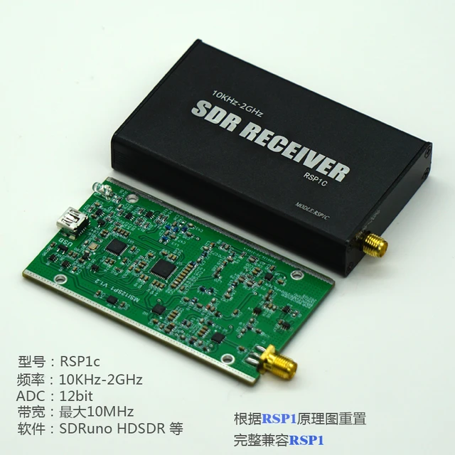
6) Ok , finally I completed the driver for the RSP1c and similar one. The driver is for Windows 10, 11. It supports the newest libusb.dll! The driver bases on the code of Miroslav Slugen and the addition of Leif Asbrink SM5BSZ. I hardly modified the code changing all the parts responsible for communication with windows. I also improved the bulk transfer and solved some issues with stability. I must say, the driver supports 99% of what I could find in Internet which is:
Done:
- 8 to 14 bits dynamic range
- 2 to10MHz bandwith
- supports band pass filters
- automatically change the LNA from one input anthena depending on the band
- supports all the compresion formats
- uses the latest libusb.dll
- both USB comunications are stable (bulk and isochronous)
- supports all the amplification modes (3 amplifiers)
- return number of lost bites
- improved memory menagement (bulk mode)
To do:
- test the asyncronius mode (is there but not tested, I did’n need this)
- amplification auto level
- not compatibile with previous versions
To use the new driver it is necesary to download the latest Radar2. This program suports the RSP1c dongle as a third reciver.
Code of Radar2 which uses the RSP1c driver. This is the latest version of radar after meny modifications. It is much faster than the first version of Radar. The Ambiguity window with size 100×100 (rows x columns) with buffer size of 1024MB is refreshed more than 120 times/s with NVIDIA 3060 (laptop). With buffer size of 4048MB it is capable to detect walking people with calculation speed of 30 calculations/s. The window frames/s are calculated separatly from the ambiguity function. The code is optimised to not block komunication between threads (40% faster now). Please, use the 64bit version. 32bit is possible but you need all the libraries (*.dll) also to be 32bit. For compilation remove the security blocking from *.resx files!
The latest Ambiguity function (a bit faster)
Radar2 uses Bing maps so if you need a fully functional bing map you have to use a map key (later I will show how to do it). Radar2 uses 4 dongles at once. The third window is dedicated to RSP1 dongle. For tests only one dongle can be used. It is also a good tool to compare RTL-SDR with RSP1. I must say it is really better device. The code in action will be soon on Youtube:)

