using TEENSY 4.0/4.1 and TCD1309 sensor
While the internet is full of TCD1304 projects using STM32F401 series chips, they typically hit a wall at 2 MHz (see one of the bests: https://www.google.com/search?q=thecuriousscientist.com). This project leverages the raw power of the Cortex-M7 (600MHz) to run the detector at 4 MHz—effectively doubling the data throughput and temporal resolution with true 1nm resolution!.
To a seasoned bare-metal pro, writing this code might be just a day’s work. For me, it was a grueling two-week marathon of debugging, reading technical manuals, and coffee breaks—but seeing that 4 MHz clock stabilize was worth every second.
The Magic of Bare Metal: Timers, Registers, and Crossbar
The secret to this speed lies in the low-level architecture:
- Clock & Register Manipulation: Instead of standard libraries, the code manipulates the Teensy’s internal clocks and registers directly to generate a rock-solid 4 MHz Master Clock (fM).
- The Crossbar (XBAR): To ensure nanosecond-perfect synchronization between the trigger signals (SH, ICG) and the ADC sampling, the project utilizes the hardware Crossbar. This allows internal signals to be routed at hardware speeds, bypassing the latency of CPU-interrupted software toggling.
- Precision Interrupts: The exposure time is not handled by a simple
delay(). It is governed by high-priority hardware interrupts that precisely time the Integration Clear Gate (ICG) and Shift Gate (SH) pulses, allowing for exposure control that is both stable and highly granular.
Bluetooth Architecture: The BTManager
To handle the firehose of data coming off the 3648-pixel sensor at such high speeds, a dedicated BTManager class was developed:
- Non-blocking Transmission: The system uses a specialized buffering strategy to ensure that wireless transmission doesn’t bottleneck the high-speed acquisition.
- Full Remote Control: The protocol supports bi-directional communication, allowing the user to adjust exposure times and gain settings on the fly via Bluetooth.
Technical Highlights:
- Framework: Written in Bare Metal C++, yet fully compatible with the Arduino IDE for ease of deployment.
- Speed: 4 MHz fM clock, significantly faster than typical STM32-based hobbyist designs.
- 12bits ADC
- Detector: Toshiba TCD1304 (3648 pixels).
- Efficiency: Optimized ADC sampling with direct memory access principles to handle the high pixel clock.
- Sending sygnal through USB or/and BlueTooth
/*
 * __________________________________________________________________________
 * |                                                                          |
 * |    _____             _  _             _    _                 _            |
 * |   / ____|           | || |           | |  | |               | |           |
 * |  | (___   _ __   ___| || |_ _ __ ___ | |__| | __ _ _ __   __| |           |
 * |   \___ \ | '_ \ / _ \ || __| '__/ _ \|  __  |/ _` | '_ \ / _` |           |
 * |   ____) || |_) |  __/ || |_| | | (_) | |  | | (_| | | | | (_| |           |
 * |  |_____/ | .__/ \___|_| \__|_|  \___/|_|  |_|\__,_|_| |_|\__,_|           |
 * |          | |                                                              |
 * |          |_|                                                              |
 * |__________________________________________________________________________|
 *
 * Low Level Spec Controller by Daniel M. Kaminski 2026
 * * Target Hardware: Teensy 4.1 (ARM Cortex-M7)
 * Sensor Support:  Toshiba TCD1304D Linear CCD
 * Max Clock Speed: 4.166 MHz
 * Application:     UV-VIS Spectroscopy
 * * Key Features:
 * - High-speed ADC ETC & DMA data transfer
 * - Precise FlexPWM clock generation (up to 20MHz command support)
 * - Real-time Auto-Exposure PID algorithm
 * - Integrated telemetry (Battery, Temperature, Humidity)
 * - High-speed Serial Binary protocol (5.0 Mbps)
 * __________________________________________________________________________
 */

#include "ADC.h"
#include "DMAChannel.h"
#include <LittleFS.h>
#include <TMCStepper.h>
#include "BTManager.h"

#define DRIVER_ADDRESS 0b00
#define Trigger_pulse_end 70
#define ble Serial1         // HM-10 podłączony do pinów 0 (RX) i 1 (TX) w Teensy 4.1


/* --- PIN DEFINITIONS --- */
const int PIN_SH = 6;
const int PIN_ICG = 7;
const int PIN_ON = 9;
const int PIN_AUTO_OFF = 32;
const int PIN_LASER_LIGHT = 23;
const int PIN_BULP_LIGHT = 19;
const int PIN_LED = 13;
const int PIN_ADC_IN = A0;      // Physical Pin 14
const int PIN_BATTERY = A2;
const int PIN_TEMP = A3;
const int PIN_VOLTAGE_CONVETER_MOTOR = 3; //przetwornica silnika krokowego
const int AUTO_OFF= 8;

// Piny dla silnika (zgodnie z ustaleniami: wyższe numery)
const int PIN_M_STEP = A4;
const int PIN_M_DIR = 2;
const int PIN_M_EN = A8;
const int PIN_M_TX = A6;
const int PIN_M_RX = A7;
const int PIN_M_DIAG = A17;


#define R_SENSE 0.11f          // Rezystor pomiarowy (standard dla TMC2209)

// Definicje poziomów jasności (dla rozdzielczości 12-bit: 0-4095)
const int BULB_OFF = 0;
const int BULB_PREHEAT = 60;   // Delikatne żarzenie
const int BULB_NORMAL = 30;  // Standardowe 3V
const int BULB_MAX_POT = 4095;  // Pełna moc baterii (7 potów)

/* --- CONFIGURATION & CONSTANTS --- */
#define CHANNELS_PER_ADC        1
#define PIXELS                  3694  // Full TCD1304 readout
#define N_SAMPLES_PER_INPUT     4096
#define DMA_BUFFER_SIZE         (CHANNELS_PER_ADC * N_SAMPLES_PER_INPUT)
#define DMA_BUFFER_SIZE_inBytes (DMA_BUFFER_SIZE * 2)
#define FLASH_CONFIG_SIZE       (1024 * 1024)

// Pamięć zewnętrzna PSRAM na bufor HDR
EXTMEM static uint16_t hdrBufferShort[PIXELS];
LittleFS_Program internalFlash;
volatile bool isShortFrame = true;
const uint16_t MAX_NORMALIZATION_VALUE = 4095; // 12-bit range

/* --- CCD TIMING PARAMETERS --- */
volatile uint32_t exposureInterruptInterval = 10000;
volatile uint32_t CLOCK_FREQ_HZ = 0;
volatile uint32_t current_CLOCK_FREQ_HZ = 3277000;
volatile uint32_t exposureDelayTime = 4000;
volatile uint32_t EXPOSURE_TIME_NS = exposureDelayTime;
volatile uint32_t current_SH_PULSE_NS = 23000;
volatile uint16_t current_CDS_PULSE_RATIO = 8;
// 1. Obliczamy czas trwania jednego piksela w nanosekundach
// 1,000,000,000 ns / (Freq * 1000) => 1,000,000 / Freq
uint32_t pixel_period_ns = 1000000UL / CLOCK_FREQ_HZ;
int32_t current_motor_position = 0;       // Globalny licznik kroków silnika


/* --- WORKING BUFFERS --- */
static uint16_t tempBuffer[PIXELS];
static uint16_t workBuffer[PIXELS];
// Bufor 32-bitowy, aby suma wielu klatek nie przekroczyła zakresu uint16
static uint32_t averagingSumBuffer[PIXELS];

// --- Sekcja buforów Bluetooth ---
uint16_t bt_safe_buffer[PIXELS];       // Gotowa klatka do wysyłki

volatile uint32_t current_avg_frame_count = 0;


bool stringComplete = false;

int lastSentPointsCount = PIXELS;
uint16_t bt_send_buffer[PIXELS]; // Tu trafiają dane po Peak Detection
uint32_t bt_averagingSumBuffer[PIXELS];
int bt_averagingCounter = 0;


/* --- AVERAGING & TELEMETRY --- */
const uint32_t AVG_COUNT = 1;
volatile uint32_t frames_accumulated = 0;
volatile bool isAutoExposureActive = false;
volatile int8_t bt_average=10;  //usrednianie ramek przed wyslaniem przez BT
float batteryVoltage = 0.0f;
float temperature = 0.0f;
float humidity = 0.0f;
uint32_t startCycles, endCycles;
bool isLightOn = false;
uint16_t average = 10;

// Inicjalizacja TMC2209 na Serial4 (Pin 16 - TX, Pin 17 - RX)
// Pamiętaj o rezystorze 1k między TX i RX dla komunikacji jedno-przewodowej UART
 TMC2209Stepper motorDriver(&Serial5, R_SENSE, 0b00);
 BTManager bt(Serial1, "SPEC"); // Domyślnie Serial1 i nazwa SPEC


/* --- PERIPHERAL HANDLERS --- */
static DMAChannel etc_adc1_dmachannel = DMAChannel();
ADC* adc = new ADC();
DMAMEM __attribute__((aligned(DMA_BUFFER_SIZE_inBytes))) static uint16_t dma_buffer_adc1[DMA_BUFFER_SIZE];
volatile bool flag_filled = 0;
IntervalTimer acquisitionTimer;

String inputString = "";

uint16_t read_buffer = 0;

struct CalibrationData
{
    bool weakPixelsMask[PIXELS];
    float hdrFactor = 1.0f;
    bool isValid = false;
}
calib;

extern "C" {
    extern void xbar_connect(unsigned int input, unsigned int output);
    extern const uint8_t pin_to_channel[];
}

// Definicja struktury ramki (nagłówek + dane)
#pragma pack(push, 1) // Wymuszenie braku wyrównania (paddingu) w strukturze
struct FramePacket {
    uint8_t sync[3];           // 0xFF, 0xFF, 0xFF
    uint32_t clock_hz;         //
    uint32_t exposure_ns;      //
    uint32_t sh_pulse_ns;      //
    int32_t motor_pos;         //
    uint16_t battery_mv;       //
    int16_t temperature_c;     //
    uint8_t flags;             //
    uint16_t separator;        // 0xBEEF
    uint16_t pixelData[PIXELS]; //
};
#pragma pack(pop)

static FramePacket txPacket; // Globalny bufor ramki

//FILTR MEDIANOWY
 // Definicja liczby klatek do mediany (3 lub 5 to złoty środek)
#define MEDIAN_WINDOW 3
// Wykorzystujemy pamięć EXTMEM (PSRAM), aby nie zabierać RAMu operacyjnego
EXTMEM static uint16_t medianHistory[MEDIAN_WINDOW][PIXELS];
int medianIndex = 0;
bool historyFull = false;

/**
 * @brief DMA Interrupt Service Routine
 * Called automatically when the DMA transfer of pixel data is complete.
 */
void dma_etc_adc_isr()
{
    endCycles = ARM_DWT_CYCCNT;
    etc_adc1_dmachannel.disable();

    // Invalidate cache to ensure we read fresh data from RAM
    arm_dcache_delete((void*)dma_buffer_adc1, sizeof(dma_buffer_adc1));
    memcpy((void*)tempBuffer, (const void*)dma_buffer_adc1, PIXELS * sizeof(uint16_t));


    flag_filled = 1; // Signal that new data is available for processing

    etc_adc1_dmachannel.clearInterrupt();
    digitalWriteFast(PIN_LED, LOW);

    asm("dsb");
}

void setupGPT1(uint32_t micros)
{
    CCM_CCGR1 |= CCM_CCGR1_GPT1_SERIAL(CCM_CCGR_ON); // Włącz zegar GPT1
    GPT1_CR = 0; // Reset
    GPT1_PR = 23; // Prescaler: 24MHz / (23+1) = 1MHz (rozdzielczość 1us)
    GPT1_OCR1 = micros - 1; // Ustaw okres
    GPT1_IR = GPT_IR_OF1IE; // Włącz przerwanie Output Compare 1
    GPT1_CR = GPT_CR_EN | GPT_CR_CLKSRC(1); // Włącz timer (zegar 24MHz)

    // Podpięcie przerwania
    _VectorsRam[IRQ_GPT1 + 16] = gpt1_isr;
    NVIC_ENABLE_IRQ(IRQ_GPT1);
}

/**
 * @brief Timer Callback for Acquisition Triggering
 * Controls the ICG/SH timing sequence to start a new CCD readout.
 */
void gpt1_isr()
{
    GPT1_SR |= GPT_SR_OF1; // Wyczyść flagę przerwania

    if (!flag_filled)
    {
        startCycles = ARM_DWT_CYCCNT;

        digitalWriteFast(PIN_LED, HIGH);

        digitalWriteFast(PIN_ICG, LOW);
        delayNanoseconds(10000);
        digitalWriteFast(PIN_ICG, HIGH);

        delayMicroseconds(EXPOSURE_TIME_NS);

        noInterrupts();
        digitalWriteFast(PIN_ICG, LOW);
        delayNanoseconds(400);
        digitalWriteFast(PIN_SH, HIGH);
        delayNanoseconds(current_SH_PULSE_NS);
        digitalWriteFast(PIN_SH, LOW);
        delayNanoseconds(400);
        digitalWriteFast(PIN_ICG, HIGH);

        etc_adc1_dmachannel.enable();
        interrupts();
    }

    // KLUCZ: Płynna zmiana okresu na żywo
    GPT1_OCR1 = exposureInterruptInterval - 1;
    asm volatile ("dsb"); // Bariera pamięci
}

/**
 * @brief Initializes the ADC hardware registers
 */
void adc_init()
{

    // ADC0 Configuration (Fast Data Capture)
    adc->adc0->setAveraging(1);
    adc->adc0->setResolution(12);
    adc->adc0->setConversionSpeed(ADC_CONVERSION_SPEED::VERY_HIGH_SPEED);
    adc->adc0->setSamplingSpeed(ADC_SAMPLING_SPEED::VERY_HIGH_SPEED);

    ADC1_CFG |= ADC_CFG_ADTRG;
    ADC1_HC0 = 16;
    ADC1_GC &= ~ADC_GC_ADCO;

    IMXRT_ADC_ETC.CTRL = ADC_ETC_CTRL_SOFTRST;
    delay(5);
    IMXRT_ADC_ETC.CTRL &= ~ADC_ETC_CTRL_SOFTRST;
}

/**
 * @brief Configures the ADC External Trigger Control (ETC)
 */
void adc_etc_setup()
{
    IMXRT_ADC_ETC.CTRL &= ~ADC_ETC_CTRL_TSC_BYPASS;
    IMXRT_ADC_ETC.CTRL |= ADC_ETC_CTRL_TRIG_ENABLE(1);
    IMXRT_ADC_ETC.TRIG[0].CTRL = ADC_ETC_TRIG_CTRL_TRIG_CHAIN(CHANNELS_PER_ADC - 1);
    IMXRT_ADC_ETC.TRIG[0].CHAIN_1_0 =
        ADC_ETC_TRIG_CHAIN_CSEL0(pin_to_channel[A0]) |
        ADC_ETC_TRIG_CHAIN_IE0(0) |
        ADC_ETC_TRIG_CHAIN_HWTS0(1);
}

/**
 * @brief Configures DMA for high-speed ADC data transfer
 */
void adc_dma_setup()
{
    etc_adc1_dmachannel.begin();
    etc_adc1_dmachannel.source(ADC_ETC_TRIG0_RESULT_1_0);
    etc_adc1_dmachannel.destinationCircular(dma_buffer_adc1, DMA_BUFFER_SIZE_inBytes);
    etc_adc1_dmachannel.TCD->NBYTES = 2;
    etc_adc1_dmachannel.TCD->DOFF = 2;
    etc_adc1_dmachannel.TCD->SOFF = 0;
    etc_adc1_dmachannel.TCD->ATTR = DMA_TCD_ATTR_SMOD(0) | DMA_TCD_ATTR_SSIZE(1) | DMA_TCD_ATTR_DMOD(13) | DMA_TCD_ATTR_DSIZE(1);

    etc_adc1_dmachannel.transferCount(N_SAMPLES_PER_INPUT);
    etc_adc1_dmachannel.triggerAtHardwareEvent(DMAMUX_SOURCE_ADC_ETC);
    etc_adc1_dmachannel.interruptAtCompletion();
    etc_adc1_dmachannel.attachInterrupt(dma_etc_adc_isr);

    ADC_ETC_DMA_CTRL = 1;
    IMXRT_ADC_ETC.CTRL |= ADC_ETC_CTRL_DMA_MODE_SEL;
}

/**
 * @brief Configures FlexPWM to generate CCD master clock and ADC triggers
 * @param frequency_hz Desired frequency for the master clock
 */
void setup_flexpwm2(float frequency_hz)
{
    // 1. Clock and MUX configuration
    CCM_CCGR4 |= CCM_CCGR4_PWM2(CCM_CCGR_ON);

    IOMUXC_SW_MUX_CTL_PAD_GPIO_EMC_06 = 1; // Pin 4 (SM2 PWMA)
    IOMUXC_SW_PAD_CTL_PAD_GPIO_EMC_06 = 0x10B0;

    IOMUXC_SW_MUX_CTL_PAD_GPIO_EMC_08 = 1; // Pin 5 (SM0 PWMA)
    IOMUXC_SW_PAD_CTL_PAD_GPIO_EMC_08 = 0x10B0;

    int slow_down = 4;
    uint16_t reload = (uint16_t)(F_BUS_ACTUAL / frequency_hz);

    // 2. Reset and stop modules
    IMXRT_FLEXPWM2.MCTRL &= ~(0xF0F);

    // --- SM0: Master CCD Clock (Pin 5) ---
    IMXRT_FLEXPWM2.SM[0].CTRL = FLEXPWM_SMCTRL_FULL;
    IMXRT_FLEXPWM2.SM[0].INIT = 0;
    IMXRT_FLEXPWM2.SM[0].VAL1 = (reload) - 1;
    IMXRT_FLEXPWM2.SM[0].VAL2 = 0;
    IMXRT_FLEXPWM2.SM[0].VAL3 = (reload) / 2; // 50% duty
    IMXRT_FLEXPWM2.SM[0].TCTRL |= FLEXPWM_SMTCTRL_OUT_TRIG_EN(1);

    // --- SM1: ADC Trigger Logic ---
    IMXRT_FLEXPWM2.SM[1].INIT = 0;
    IMXRT_FLEXPWM2.SM[1].VAL1 = (reload * slow_down) - 1;
    IMXRT_FLEXPWM2.SM[1].VAL4 = 200; // Trigger pulse start
    IMXRT_FLEXPWM2.SM[1].VAL5 = Trigger_pulse_end; // Trigger pulse end
    IMXRT_FLEXPWM2.SM[1].TCTRL = FLEXPWM_SMTCTRL_OUT_TRIG_EN(1 << 1);

    // 3. Enable physical outputs
    IMXRT_FLEXPWM2.OUTEN |= (1 << (0 + 8)); // PWMA0 (Pin 5)
    IMXRT_FLEXPWM2.OUTEN |= (1 << (2 + 8)); // PWMA2 (Pin 4)

    // 4. XBAR Cross-triggering setup
    CCM_CCGR2 |= CCM_CCGR2_XBAR1(CCM_CCGR_ON);
    xbar_connect(XBARA1_IN_FLEXPWM2_PWM2_OUT_TRIG0, XBARA1_OUT_ADC_ETC_TRIG00);

    // 5. Synchronized Start
    uint16_t mask = (1 << 0) | (1 << 1) | (1 << 2);
    IMXRT_FLEXPWM2.MCTRL |= FLEXPWM_MCTRL_LDOK(mask);
    IMXRT_FLEXPWM2.MCTRL |= FLEXPWM_MCTRL_RUN(mask);
}


/**
 * @brief Updates the CCD and Trigger frequencies at runtime
 */
void updateSystemFrequency(uint32_t frequency_hz)
{
    uint16_t reload = (uint16_t)(F_BUS_ACTUAL / frequency_hz);
    const int slow_down = 4;

    IMXRT_FLEXPWM2.SM[0].VAL1 = reload - 1;
    IMXRT_FLEXPWM2.SM[0].VAL3 = reload / 2;

    IMXRT_FLEXPWM2.SM[1].VAL1 = (reload * slow_down) - 1;
    IMXRT_FLEXPWM2.SM[1].VAL5 = Trigger_pulse_end;

    IMXRT_FLEXPWM2.SM[2].VAL1 = reload - 1;
    IMXRT_FLEXPWM2.SM[2].VAL3 = reload / 2;

    uint16_t mask = (1 << 0) | (1 << 1) | (1 << 2);
    IMXRT_FLEXPWM2.MCTRL |= FLEXPWM_MCTRL_LDOK(mask);

}

/**
 * @brief Reads auxiliary sensors (Battery, Temp, Humidity)
 */
void readAndStoreMetadata()
{
    float alpha = 0.1f;
    uint16_t raw_batt = adc->adc1->analogRead(PIN_BATTERY);
    float temp_batt = ((float)raw_batt * 3.3f / 4096.0f) * 2.0f;
    batteryVoltage =  alpha*temp_batt + (1.0f-alpha) * batteryVoltage;

    uint16_t raw_temp = adc->adc1->analogRead(PIN_TEMP);
    float temp_tmp = ((float)raw_temp * 100 / 4096.0f) / 100.0f * 25.0;
    temperature =   alpha*temp_tmp + (1.0f-alpha)* temperature;

     bt.header.battery_mv = batteryVoltage*100;
     bt.header.temperature_c = temperature*100;

}

void corection_first18Pixels() {
    uint32_t blackSum = 0;
    for (int i = 0; i < 18; i++) {
        blackSum += workBuffer[i]; // Używamy uśrednionych danych z workBuffer [cite: 20]
    }
    uint16_t darkOffset = (uint16_t)(blackSum / 18);

    // Odejmij offset od całego widma (z zabezpieczeniem przed wynikiem ujemnym)
    for (int i = 0; i < PIXELS; i++) {
        if (workBuffer[i] > darkOffset) {
            workBuffer[i] -= darkOffset;
        } else {
            workBuffer[i] = 0;
        }
    }
}


void saveCalibration()
{
    if (!internalFlash.begin(FLASH_CONFIG_SIZE))
    {
        internalFlash.quickFormat();
        if (!internalFlash.begin(FLASH_CONFIG_SIZE)) return;
    }
    File file = internalFlash.open("/sensor_cal.bin", FILE_WRITE);
    if (file)
    {
        file.write((const uint8_t*)&calib, sizeof(calib));
        file.close();
    }
}

void loadCalibration()
{
    if (internalFlash.begin(FLASH_CONFIG_SIZE))
    {
        File file = internalFlash.open("/sensor_cal.bin", FILE_READ);
        if (file)
        {
            file.read((uint8_t*)&calib, sizeof(calib));
            file.close();
        }
    }
}

int count_Send = 0;
/**
 * @brief Sends captured CCD data and metadata over Serial in binary format
 */
void sendBinaryFrame()
{
    // 1. Akumulacja danych z workBuffer do sumatora 32-bitowego
    // workBuffer zawiera aktualnie odczytaną klatkę z DMA
    for (int i = 0; i < PIXELS; i++) {
        averagingSumBuffer[i] += workBuffer[i];
    }
    frames_accumulated++; // Zwiększamy licznik zebranych klatek

    // 2. Sprawdzenie, czy uzbieraliśmy już odpowiednią liczbę klatek (np. 6)
    // Możesz tu wpisać na sztywno 6 lub użyć zmiennej 'average'
    if (frames_accumulated < 6) {
        return; // Wyjdź z funkcji, nie wysyłaj jeszcze nic
    }

    // 3. Jeśli limit został osiągnięty – obliczamy średnią bezpośrednio do bufora paczki
    for (int i = 0; i < PIXELS; i++) {
        txPacket.pixelData[i] = (uint16_t)(averagingSumBuffer[i] / frames_accumulated);
        averagingSumBuffer[i] = 0; // Resetujemy sumator dla kolejnej serii
    }

    // 4. Wypełnianie nagłówka ramki (Metadata)
    txPacket.sync[0] = 0xFF;
    txPacket.sync[1] = 0xFF;
    txPacket.sync[2] = 0xFF;


    // Przykładowe wartości (możesz tu podstawić odczyty z ADC1)
    txPacket.battery_mv =  batteryVoltage*100;
    txPacket.temperature_c = temperature*100;


    txPacket.flags = 0;
    if (isAutoExposureActive) txPacket.flags |= (1 << 0);
    if (isLightOn) txPacket.flags |= (1 << 1);

    bt.header.flags=txPacket.flags ;

    txPacket.separator = 0xBEEF;

    // 5. Błyskawiczna wysyłka całej struktury jako jeden blok danych
    // sizeof(txPacket) automatycznie wyliczy rozmiar nagłówka + 3694 pikseli
    Serial.write((uint8_t*)&txPacket, sizeof(txPacket));

    // 6. Reset licznika klatek po wysyłce
    frames_accumulated = 0;
}


/**
 * @brief Inverts and processes raw pixel data from the buffer
 */
void readAndProcessLine_new()
{
    memcpy((void*)workBuffer, (void*)tempBuffer, PIXELS * sizeof(uint16_t));


    flag_filled = false; // Release lock for next frame

    uint32_t totalCycles = endCycles - startCycles;
    float timePerClockSec = (float)totalCycles / (float)(F_CPU_ACTUAL);
    CLOCK_FREQ_HZ = 1000 * timePerClockSec;


    EXPOSURE_TIME_NS = exposureDelayTime;
    readAndStoreMetadata();

    // 3. Korekcja czerni przed wysyłką
     //   corection_first18Pixels();
     sendBinaryFrame();

     // Wykonaj uśrednianie klatek
     processAveragingAndBT();
      // Jeśli minęło 5s, wysyłaj ramkę (korzystając z naszej bezpiecznej izolacji buforów)

    runAutoExposure(); // Normalne AE

    return;

}


/* --- COMMAND INTERPRETER --- */

constexpr uint32_t str_hash(const char* s) {
    uint32_t h = 2166136261u;
while (*s) { h ^= static_cast<uint32_t>(*s++); h *= 16777619u; }
return h;
}

/**
 * @brief Parses incoming serial commands
 */
void processCommand()
{
    if (!stringComplete) return;
    inputString.trim();
    String cmd = inputString;
    cmd.toUpperCase();

    String prefix = "";
    //Serial.println("w komand analizer");
    //Serial.println(inputString);

    if (cmd.startsWith("CLK")) prefix = "CLK";
    else if (cmd.startsWith("SETE")) prefix = "SETE";
    else if (cmd.startsWith("SETAVG")) prefix = "SETAVG";
    else if (cmd.startsWith("SHP")) prefix = "SHP";
    else if (cmd.startsWith("CALCLR")) prefix = "CAL";
    else if (cmd.startsWith("LEARN")) prefix = "LEA";
    else if (cmd.startsWith("AE_OFF")) prefix = "AEF";
    else if (cmd.startsWith("AE_ON")) prefix = "AEO";
    else if (cmd.startsWith("RATIO")) prefix = "RAT";
    else if (cmd.startsWith("MOVE")) prefix = "MOV";
    else if (cmd.startsWith("AVE")) prefix = "AVE";
    else if (cmd.startsWith("POWER")) prefix = "POW";
    else if (cmd.startsWith("BTAVE")) prefix = "BAV";
    else prefix = cmd;

    switch (str_hash(prefix.c_str()))
    {

        case str_hash("RAT"):
            {
                uint32_t new_period = cmd.substring(5).toInt();
                if (new_period >= 6 && new_period <= 300)
                    exposureInterruptInterval = new_period * 1000;

                 bt.header.current_CDS_PULSE_RATIO =  new_period ;

            }
            break;

        case str_hash("AEO"):
            isAutoExposureActive = true;
            break;

        case str_hash("AEF"):
            isAutoExposureActive = false;
            break;

        case str_hash("LEA"):
            //  PixelsCalibration();
            break;

        case str_hash("CAL"):
            {
                calib.isValid = false;
                internalFlash.remove("/sensor_cal.bin");
            }
            break;

        case str_hash("CLK"):
            {
                uint32_t freq = cmd.substring(3).toInt();
                if (freq >= 1000000 && freq <= 50000000)
                {
                    current_CLOCK_FREQ_HZ = freq;
                    bt.header.current_CLOCK_FREQ_HZ= current_CLOCK_FREQ_HZ;
                    updateSystemFrequency(current_CLOCK_FREQ_HZ);
                }
                break;
            }
        case str_hash("SETE"):
            exposureDelayTime = cmd.substring(4).toInt();
            bt.header.exposureDelayTime= (uint16_t)exposureDelayTime;

            break;
        case str_hash("SHP"):
            current_SH_PULSE_NS = cmd.substring(3).toInt();

            break;
        // Dodaj wewnątrz switch (str_hash(prefix.c_str())) [cite: 90]
        case str_hash("MOV"):
            {
                int steps = cmd.substring(4).toInt();
                current_motor_position += steps; // Śledzenie pozycji dla dekonwolucji

                // 1. Włącz przetwornicę 12V (Pin 3)
                digitalWrite(PIN_VOLTAGE_CONVETER_MOTOR, HIGH);
                delay(10); // Daj przetwornicy chwilę na start

                digitalWrite(PIN_M_DIR, steps > 0);
                digitalWrite(PIN_M_EN, LOW); // Włącz cewki

                for (int i = 0; i < abs(steps); i++)
                {
                    digitalWrite(PIN_M_STEP, HIGH);
                    delayMicroseconds(800);
                    digitalWrite(PIN_M_STEP, LOW);
                    delayMicroseconds(800);
                }

                digitalWrite(PIN_M_EN, HIGH); // Wyłącz cewki (cisza dla sensora)
                // 2. Wyłącz przetwornicę 12V (Pin 3)
                digitalWrite(PIN_VOLTAGE_CONVETER_MOTOR, LOW);
            }
            break;
        case str_hash("AVE"):
            {
                uint16_t ave = cmd.substring(3).toInt();
                if (ave >= 1 && ave<= 100)
                {
                    average = ave;
                }
            }
             break;
        case str_hash("POW"):
            {
                uint32_t power= cmd.substring(5).toInt();
                if (power >= 1 && power <= 4096)
                {
                    analogWrite(PIN_LASER_LIGHT, power);
                    bt.header.power=power;
                }
                break;
            }
            case str_hash("BAV"):
            {
                uint8_t tmp = cmd.substring(5).toInt();
                if (tmp >= 1 && tmp <= 100)
                {
                    bt_average = tmp;
                    bt.header.average=tmp;
                }
                break;
            }

        case str_hash("AUTOON"): isAutoExposureActive = true; break;
        case str_hash("AUTOOFF"): isAutoExposureActive = false; break;
        case str_hash("LTRON"): bulbControl(1); bulbControl(2); break;
        case str_hash("LTROFF"): bulbControl(0); break;
    }
    inputString = "";
    stringComplete = false;
}


/**
 * @brief PID-like algorithm to adjust exposure based on image brightness
 * @param currentPeakValue The highest intensity value found in the current frame
 */
void runAutoExposure()
{
    // 1. Zabezpieczenia
    if (!isAutoExposureActive || bt.isSending) return;
    if (calib.isValid && !isShortFrame) return;

    // 2. Parametry - "Więcej luzu"
    const uint32_t MIN_INTERRUPT_VAL = 200;
    const uint32_t MAX_TOTAL_VAL     = 48000000;
    const uint16_t OPTIMUM_TARGET    = 3600;
    const uint16_t SATURATION_LIMIT  = 4080;
    const uint16_t BACKGROUND_LEVEL  = 30;

    // Zwiększony luz: w zakresie 3540 - 3660 algorytm w ogóle nie dotyka rejestrów
    const uint16_t DEADZONE          = 60;

    // 3. Szukanie PeakValue
    uint16_t currentPeakValue = 0;
    for (uint32_t i = 20; i < PIXELS - 20; i++)
    {
        if (workBuffer[i] > currentPeakValue) currentPeakValue = workBuffer[i];
    }

    // 4. Obliczanie aktualnego czasu całkowitego
    uint32_t currentTotal = (exposureInterruptInterval > exposureDelayTime) ? (exposureInterruptInterval - exposureDelayTime) : 100;
    uint32_t targetTotal = currentTotal;

    // 5. Analiza błędu
    int32_t error = (int32_t)OPTIMUM_TARGET - (int32_t)currentPeakValue;

    // Czy jesteśmy w nasyceniu? (Tu nie ma luzu, trzeba uciekać)
    if (currentPeakValue >= SATURATION_LIMIT)
    {
        targetTotal = currentTotal / 2;
    }
    // Czy błąd jest na tyle duży, że musimy reagować?
    else if (abs(error) > DEADZONE)
    {
        float ratio = (float)OPTIMUM_TARGET / (float)currentPeakValue;
        uint32_t calculated = (uint32_t)((float)currentTotal * ratio);

        // Bardzo łagodne alpha blisko celu (tłumienie drgań)
        float alpha;
        if (abs(error) < 150) {
            alpha = (error > 0) ? 0.005f : 0.015f; // Super powolna adaptacja
        } else {
            alpha = (error > 0) ? 0.03f : 0.10f;  // Spokojna reakcja
        }

        targetTotal = currentTotal + (int32_t)(alpha * (int32_t)(calculated - currentTotal));
    }
    else
    {
        // Jesteśmy w strefie komfortu - nic nie robimy
        return;
    }

    // 6. Limity
    if (targetTotal > MAX_TOTAL_VAL) targetTotal = MAX_TOTAL_VAL;
    if (targetTotal < 100) targetTotal = 100;

    // 7. Podział na Interwał i Delay (95%)
    uint32_t nextInterruptVal = (targetTotal * 105) / 100;
    if (nextInterruptVal < MIN_INTERRUPT_VAL) nextInterruptVal = MIN_INTERRUPT_VAL;

    int32_t calculatedDelay = (int32_t)nextInterruptVal - (int32_t)targetTotal;
    uint32_t maxDelay = (nextInterruptVal * 95) / 100;

    if (calculatedDelay < 0) calculatedDelay = 0;
    if ((uint32_t)calculatedDelay > maxDelay) calculatedDelay = maxDelay;

    // 8. Ostateczny filtr stabilności
    // Zmiana musi być większa niż 0.5% wartości, żeby w ogóle ruszyć rejestr timera.
    // To zabija "taniec" wywołany szumem ADC.
    if (abs((int32_t)targetTotal - (int32_t)currentTotal) < (currentTotal / 200)) return;

    exposureDelayTime = (uint32_t)calculatedDelay;

    if (exposureInterruptInterval != nextInterruptVal) {
        exposureInterruptInterval = nextInterruptVal;
        GPT1_OCR1 = exposureInterruptInterval - 1;
    }
}


void bulbControl(int mode)
{
    switch (mode)
    {
        case 0: // CAŁKOWITE WYŁĄCZENIE
            analogWrite(PIN_LASER_LIGHT, BULB_OFF);
            break;

        case 1: // MIĘKKI START DO NORMALNEJ PRACY
                // Ramp-up: chroni włókno przed udarem prądowym
            for (int i = 0; i <= BULB_NORMAL; i++)//
            {
                analogWrite(PIN_LASER_LIGHT, i);
                delay(80); // Cały start trwa ok. 120ms
            }
            break;

        case 2: // TRYB POMIAROWY (BOOST)
                // Jeśli żarówka była wyłączona, najpierw zrób pre-heat
            analogWrite(PIN_LASER_LIGHT, BULB_PREHEAT);
            delay(100);

            // Skok do "7 potów"
            analogWrite(PIN_LASER_LIGHT, BULB_MAX_POT);

            // Krótka pauza na stabilizację temperatury włókna przed odczytem CCD
            delay(150);
            break;
    }
}


// Szybka funkcja sortująca 3 liczby i zwracająca środkową
inline uint16_t getMedian3(uint16_t a, uint16_t b, uint16_t c) {
    if ((a <= b && b <= c) || (c <= b && b <= a)) return b;
    if ((b <= a && a <= c) || (c <= a && a <= b)) return a;
    return c;
}


/**
 * @brief Logika filtracji medianowej, uśredniania i wyzwalania wysyłki przez BT
 */
void processAveragingAndBT() {
    // Sprawdzamy, czy BTManager aktualnie nie wysyła danych
    if (bt.isSending  )
        return;


    // 1. Zapisujemy bieżącą klatkę (workBuffer) do historii mediany
    memcpy(medianHistory[medianIndex], workBuffer, PIXELS * sizeof(uint16_t));
    medianIndex = (medianIndex + 1) % MEDIAN_WINDOW;

    // Sprawdzamy czy mamy wystarczająco klatek, by zacząć proces
    if (!historyFull) {
        if (medianIndex == 0) historyFull = true;
        else return; // Czekamy na zapełnienie pierwszego okna 3 klatek
    }

    // 2. Akumulacja danych po przejściu przez filtr medianowy
    for (int i = 0; i < PIXELS; i++) {
        // Wyciągamy medianę - to tutaj "wycinamy" kwadratowe piki od BT
        uint16_t cleanValue = getMedian3(
            medianHistory[0][i],
            medianHistory[1][i],
            medianHistory[2][i]
        );

        bt_averagingSumBuffer[i] += cleanValue;
    }
    bt_averagingCounter++;

    // 3. Jeśli osiągnęliśmy limit uśrednień (zadany przez bt_average)
    if (bt_averagingCounter >= bt_average) {

        int pointsToSend = 0;

        // Przechodzimy przez całe spektrum z krokiem bt.PackingMode (np. PAK1, PAK2...)
        for (int i = 0; i < PIXELS; i += bt.PackingMode) {

            uint16_t maxVal = 0;

            // Szukamy najwyższej wartości w oknie (Peak Detection)
            for (int k = 0; k < bt.PackingMode; k++) {
                if ((i + k) < PIXELS) {
                    // Obliczamy średnią z przefiltrowanych wcześniej danych
                    uint16_t currentPointAvg = (uint16_t)(bt_averagingSumBuffer[i + k] / bt_averagingCounter);
                    if (currentPointAvg > maxVal) {
                        maxVal = currentPointAvg;
                    }
                }
            }

            // Zapisujemy czysty punkt do bufora wysyłkowego
            bt_send_buffer[pointsToSend] = maxVal;
            pointsToSend++;
        }

        // Zapisujemy c:\Users\danie\Dokumenty\Arduino\LowLevelSpec2.ino\BTManager.hliczbę punktów dla ewentualnej retransmisji
        lastSentPointsCount = pointsToSend;


        // 4. Reset akumulatora uśredniania (nie czyścimy historii mediany!)
        memset(bt_averagingSumBuffer, 0, sizeof(bt_averagingSumBuffer));
        bt_averagingCounter = 0;
    }
}


/**
 * @brief Main setup function
 */
void setup()
{

    Serial.begin(1000000);
    while (!Serial && millis() < 2000) ;

    //BT
    bt.SetupBT();

    Serial5.begin(115200);  // UART do TMC2209 na pinach 16 i 17

    pinMode(PIN_M_STEP, OUTPUT);
    pinMode(PIN_M_DIR, OUTPUT);
    pinMode(PIN_M_EN, OUTPUT);
    pinMode(PIN_VOLTAGE_CONVETER_MOTOR, OUTPUT);

    digitalWrite(PIN_M_EN, HIGH); // Driver wyłączony na starcie
    digitalWrite(PIN_VOLTAGE_CONVETER_MOTOR, LOW); // Przetwornica silnika krokowego wyłączona na starcie
    // Konfiguracja drivera przez UART
     motorDriver.begin();
     motorDriver.rms_current(50); // Bezpieczny prąd 50mA
     motorDriver.toff(4);


    pinMode(PIN_SH, OUTPUT);
    pinMode(PIN_ICG, OUTPUT);
    pinMode(PIN_LED, OUTPUT);
    pinMode(PIN_ON, OUTPUT);
    pinMode(PIN_LASER_LIGHT, OUTPUT);

    digitalWriteFast(PIN_ON, HIGH);
    digitalWriteFast(PIN_ICG, HIGH);
    digitalWriteFast(PIN_SH, LOW);

    adc_init();

    adc_etc_setup();
    adc_dma_setup();

    // ADC1 Configuration (Sensors / Metadata)
    adc->adc1->setAveraging(4);
    adc->adc1->setResolution(12);

    setup_flexpwm2(current_CLOCK_FREQ_HZ);

    // Start acquisition cycle every 100ms
    setupGPT1(exposureInterruptInterval);

    //Zarowka
     analogWriteRes(12);

    // Wysoka częstotliwość, aby uniknąć migotania widocznego dla TCD1304
    // 14648.437 Hz to idealna częstotliwość dla Teensy 4.1 przy 12-bitach
    analogWriteFrequency(PIN_LASER_LIGHT, 10000);
    analogWrite(PIN_LASER_LIGHT, 0);

    bt.header.current_CLOCK_FREQ_HZ= (uint16_t)current_CLOCK_FREQ_HZ;
    bt.header.exposureDelayTime=exposureDelayTime; // 15, 16
    bt.header.current_CDS_PULSE_RATIO=current_CDS_PULSE_RATIO;  // 17, 18
}


/**
 * @brief Main execution loop
 */
void loop()
{
    while (Serial.available())
    {
        char inChar = (char)Serial.read();
        inputString += inChar;
        if (inChar == '\n') stringComplete = true;
    }


// 2. Odczyt z Bluetooth przez klasę BTManager
    // Jeśli metoda zwróci tekst (np. "PAK1"), traktujemy to jak wejście z USB
    // NASŁUCHIWANIE: Tu klasa sprawdza, czy z telefonu przyszło:
    // 'G' -> wyślij ponownie ostatnią klatkę
    // 'R' -> powtórz konkretną paczkę (Retransmisja)
    // 'D' -> zmień delay
    String btInput = bt.HandleCommunication(bt_send_buffer, lastSentPointsCount);

    if (btInput.length() > 0) {
        //   Serial.println(btInput);
        inputString = btInput;
        stringComplete = true;
    }
    //process heartbeat
    bt.update();


    processCommand();

    if (flag_filled)
    {
        readAndProcessLine_new();
    }


}
The red line represents the LED light at full speed.
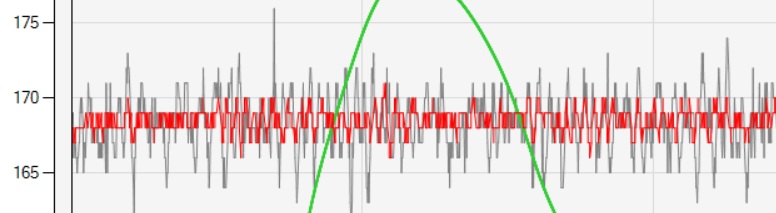
The noise floor is clearly visible in the image: the grey line represents a single raw frame with a noise level of approximately ±10 pixels. The red line shows the result after averaging 10 readings, which significantly reduces the noise to just ±2 pixels. This demonstrates the high stability of the Teensy-based acquisition system (30 frames/s).
Currently, the system uses a highly stable Bluetooth transmission algorithm optimized for the HM-10 module. However, as the project is soon transitioning to a dedicated ESP32 co-processor for wireless communication, the specific Bluetooth library is not included in this release. This migration will further enhance data throughput and connectivity options.
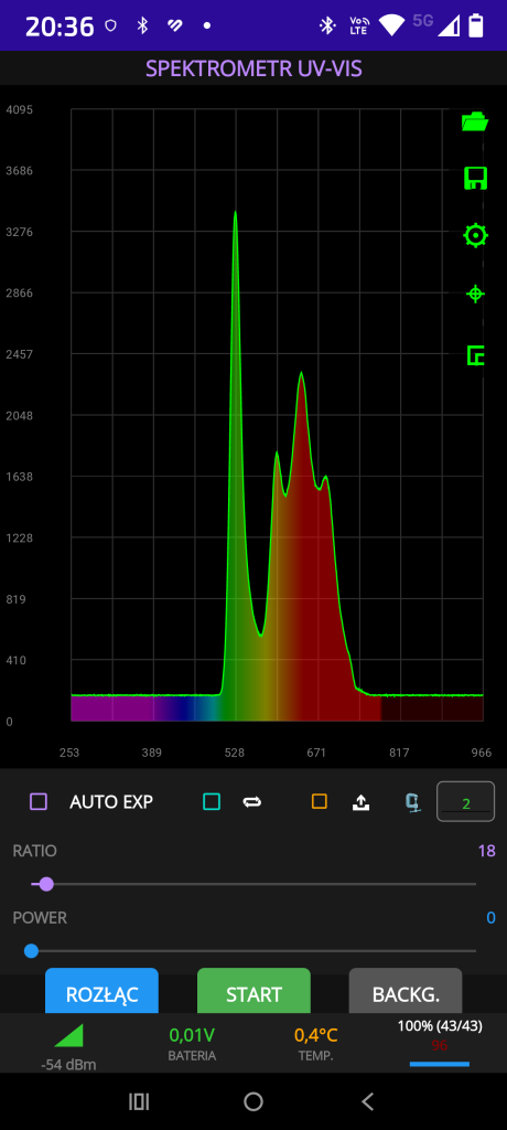
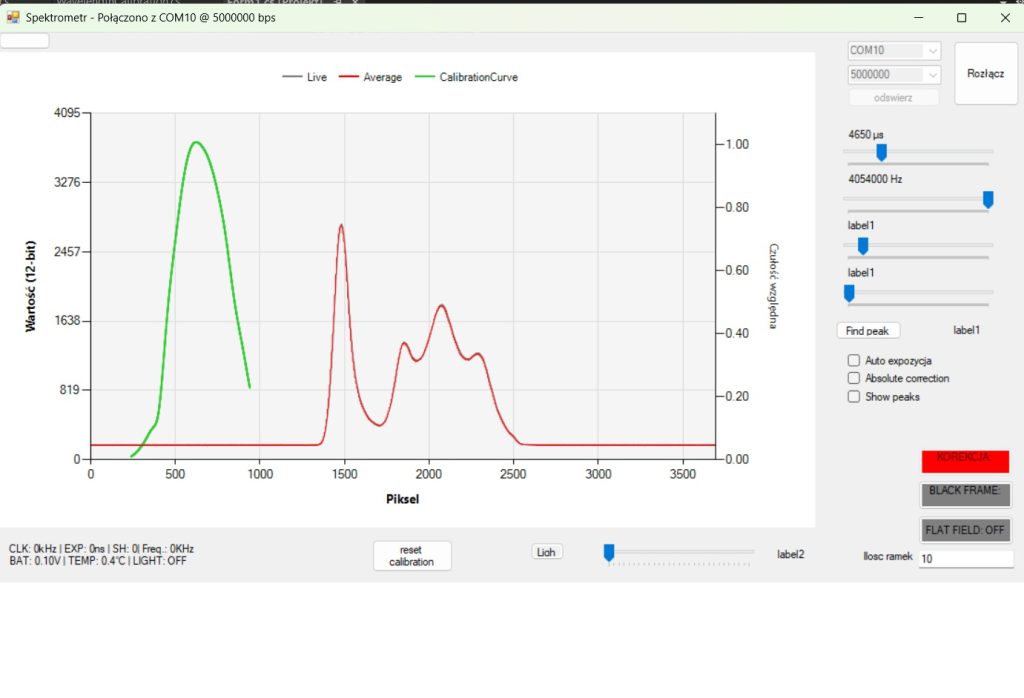
Full Ecosystem: Android Integration & Optical Precision
While the bare-metal code handles the raw data, the true power of this spectrometer is unleashed through a fully functional Android application. This mobile station transforms the Teensy-based sensor into a professional-grade laboratory tool.
Advanced Software Features:
- Absolute Spectral Correction: The app doesn’t just show raw counts; it applies absolute calibration to provide scientifically accurate spectral data.
- Professional Measurement Workflow: Integrated functions for Background Subtraction (Dark Frame) and Flat-Field Correction to eliminate sensor non-uniformity.
- Cloud Integration: Seamless data export directly to Google Drive for further analysis, along with the ability to load and compare multiple spectra in real-time.
- Bi-directional BT Communication: Full remote control over the spectrometer’s parameters (exposure, gain, triggers) via a robust custom protocol.
- 3 points calibration
Advanced Spectral Calibration
To achieve scientific-grade accuracy, the system implements a 3-point wavelength calibration mechanism. Unlike simple linear scaling, our software utilizes a 2nd-degree polynomial (quadratic function) to map pixel positions to nanometers.
- Quadratic Mapping: By using three reference points (e.g., from a calibration lamp), the algorithm calculates the coefficients of a parabola: lambda(p) = ap2 + bp + c p is the pixel index and lambda is the corresponding wavelength.
- Precision: This approach compensates for the inherent non-linearity of the optical path, ensuring that every peak across the entire UV-VIS range is exactly where it should be.
Dealing with Optical Artifacts: Etaloning
As seen in the provided image, the raw signal often exhibits a characteristic „wavy” pattern known as Etaloning (or fringing). This interference effect occurs within the detector’s cover glass or the CCD structure itself, especially in the NIR/UV regions. Our software is designed to recognize and compensate for these patterns, ensuring that the final output represents the true characteristics of the light source.
The Connectivity Roadmap: From HM-10 to ESP32
Currently, the device utilizes a rock-solid transmission algorithm optimized for HM-10 Bluetooth modules. This ensures stable data flow for the current version.
Note: The specific Bluetooth library is intentionally omitted from the current source code release, as the project is transitioning to a dedicated ESP32 co-processor. This move will significantly boost wireless bandwidth and allow for even higher frame rates.
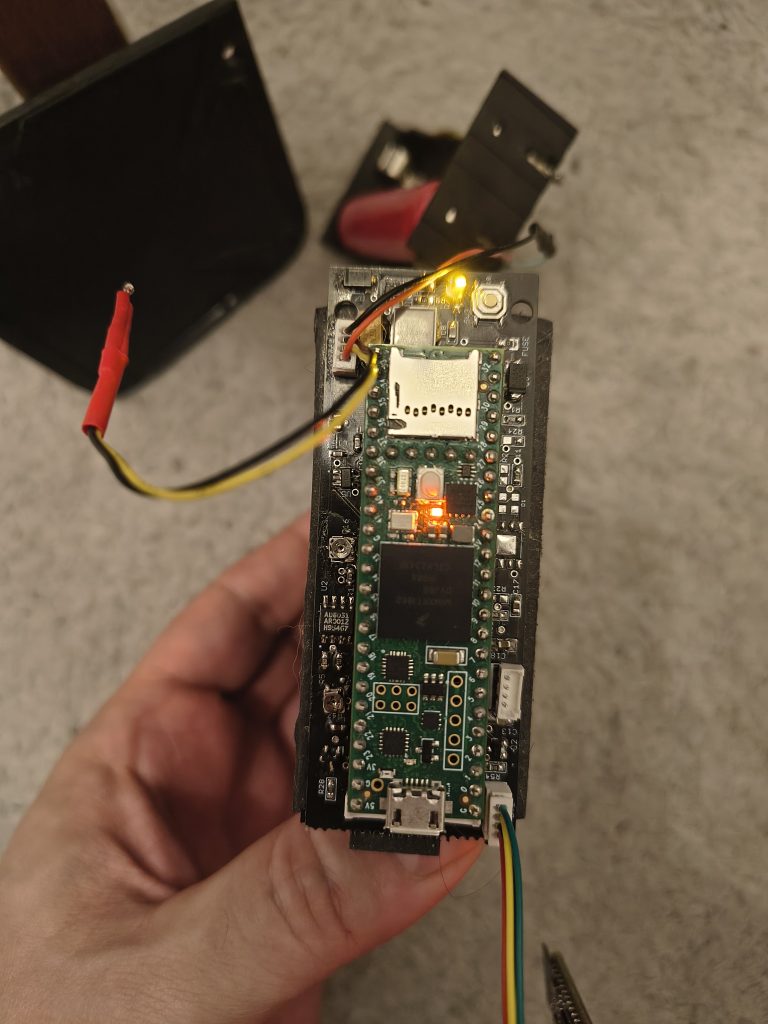
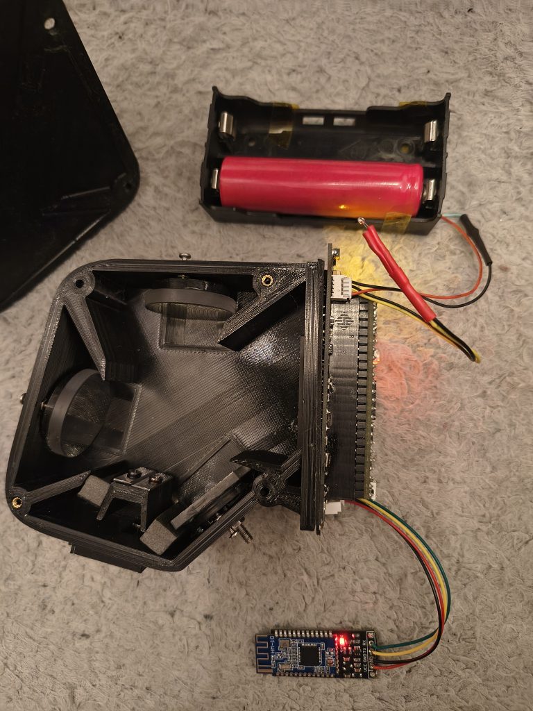
Hardware Autonomy & Advanced Control Features
The project has evolved into a fully stand-alone device, capable of conducting field measurements without a permanent connection to a workstation.
Power Management & Portability
- Battery Powered: The system operates independently on a built-in battery, making it truly portable.
- Integrated Charging: Charging is handled via a standard USB port, allowing for easy power-ups from a laptop or power bank.
- Electronic Soft-Switch: The device features a professional power management circuit – it can be turned on and off via a dedicated soft-touch button („na puszcie”), ensuring clean power transitions.
Programmable Optical & Mechanical Control
Everything is integrated into the Teensy-based motherboard and can be controlled directly from the software:
- Calibration Light Sources: Support for calibration LEDs and a standard incandescent bulb (used for flat-fielding) is fully integrated. Both are software-controlled for automated measurement sequences.
- Motorized Slit Control: One of the most advanced features is the programmable slit width control. The motherboard includes a servo driver that allows the user to adjust the optical resolution of the spectrometer remotely via the application.
Join the Development
This project is continuously evolving. If you are a developer, researcher, or spectroscopy enthusiast interested in contributing to the code, hardware design, or the Android ecosystem, I invite you to get in touch. Let’s push the boundaries of DIY spectroscopy together!
The Next Step: Ergonomic Field Housing
To transition from a laboratory prototype to a field-ready instrument, we are currently designing a bespoke 3D-printed enclosure. The focus is on extreme portability and optical integrity:
Ruggedness: Designed to be printed in matte black ASA for thermal stability and superior stray-light absorption.
Light-tight Compartmentalization: Separate chambers for high-speed electronics and the sensitive TCD1304 optical path.
Field Ergonomics: A compact, rounded design featuring an integrated soft-touch power button and a protected USB charging port.
Smart Mechanics: The housing includes dedicated mounting points for the servo-controlled slit mechanism and internal baffles to eliminate stray light.