
using TEENSY 4.0/4.1 and TCD1309 sensor
While the internet is full of TCD1304 projects using STM32F401 series chips, they typically hit a wall at 2 MHz (see one of the bests: https://www.google.com/search?q=thecuriousscientist.com). This project leverages the raw power of the Cortex-M7 (600MHz) to run the detector at 4 MHz—effectively doubling the data throughput and temporal resolution with true 1nm resolution!.
To a seasoned bare-metal pro, writing this code might be just a day’s work. For me, it was a grueling two-week marathon of debugging, reading technical manuals, and coffee breaks—but seeing that 4 MHz clock stabilize was worth every second.
The Magic of Bare Metal: Timers, Registers, and Crossbar
The secret to this speed lies in the low-level architecture:
- Clock & Register Manipulation: Instead of standard libraries, the code manipulates the Teensy’s internal clocks and registers directly to generate a rock-solid 4 MHz Master Clock (fM).
- The Crossbar (XBAR): To ensure nanosecond-perfect synchronization between the trigger signals (SH, ICG) and the ADC sampling, the project utilizes the hardware Crossbar. This allows internal signals to be routed at hardware speeds, bypassing the latency of CPU-interrupted software toggling.
- Precision Interrupts: The exposure time is not handled by a simple
delay(). It is governed by high-priority hardware interrupts that precisely time the Integration Clear Gate (ICG) and Shift Gate (SH) pulses, allowing for exposure control that is both stable and highly granular.
Bluetooth Architecture: The BTManager
To handle the firehose of data coming off the 3648-pixel sensor at such high speeds, a dedicated BTManager class was developed:
- Non-blocking Transmission: The system uses a specialized buffering strategy to ensure that wireless transmission doesn’t bottleneck the high-speed acquisition.
- Full Remote Control: The protocol supports bi-directional communication, allowing the user to adjust exposure times and gain settings on the fly via Bluetooth.
Technical Highlights:
- Framework: Written in Bare Metal C++, yet fully compatible with the Arduino IDE for ease of deployment.
- Speed: 4 MHz fM clock, significantly faster than typical STM32-based hobbyist designs.
- 12bits ADC
- Detector: Toshiba TCD1304 (3648 pixels).
- Efficiency: Optimized ADC sampling with direct memory access principles to handle the high pixel clock.
- Sending sygnal through USB or/and BlueTooth
Bare metal code for USB PC connection
Below is the complete, fully production-ready firmware driving the spectrometer, specifically optimized for the Teensy 4.0 and 4.1. This version is streamlined exclusively for high-speed USB communication with a PC. For the sake of code clarity, I have stripped out the ESP32-C3-based Bluetooth module from this release. The code has been thoroughly tested and is ready to compile seamlessly within the Arduino IDE. Just make sure you have the Teensy board manager installed along with a couple of missing external libraries (you might need to grab 1 or 2, depending on your setup). Let’s dive into the code:
 /*
* ===========================================================================
*   Low Level Spec Controller by Daniel M. Kaminski 2026
*   Version: 1.3
*   Date: 25.03.2026
*
*   Target Hardware: Teensy 4.1 (ARM Cortex-M7)
*   Sensor: Toshiba TCD1304D Linear CCD
*   Max Clock Speed: 4.166 MHz
*   Application: UV-VIS Spectroscopy
*
*   Key Features:
*   - High-speed ADC ETC & DMA data transfer
*   - Precise FlexPWM clock generation (up to 20MHz command support)
*   - Real-time Auto-Exposure PID algorithm
*   - Integrated telemetry (Battery, Temperature)
*   - High-speed Serial Binary protocol over USB
* ===========================================================================
*/

#include "ADC.h"
#include "DMAChannel.h"
#include <LittleFS.h>
#include <TMCStepper.h>


#define DRIVER_ADDRESS 0b00
#define Trigger_pulse_end 70

/* --- PIN DEFINITIONS --- */
const int PIN_SH = 6;
const int PIN_ICG = 7;
const int PIN_ON = 9;
const int PIN_AUTO_OFF = 32;
const int PIN_BULP_LIGHT = 23;
const int PIN_LASER_LIGHT = 19;
const int PIN_LED = 13;
const int PIN_ADC_IN = A0;
const int PIN_BATTERY = A1;
const int PIN_TEMP = A2;
const int PIN_VOLTAGE_CONVETER_MOTOR = 3;
const int AUTO_OFF = 8;

// Motor pins
const int PIN_M_STEP = A4;
const int PIN_M_DIR = 2;
const int PIN_M_EN = A8;
const int PIN_M_TX = A6;
const int PIN_M_RX = A7;

#define R_SENSE 0.11f

// Brightness levels (12-bit: 0-4095)
const int BULB_OFF = 0;
const int BULB_PREHEAT = 60;
const int BULB_NORMAL = 30;
const int BULB_MAX_POT = 4095;

/* --- CONFIGURATION & CONSTANTS --- */
#define CHANNELS_PER_ADC        1
#define PIXELS                  3694
#define N_SAMPLES_PER_INPUT     4096
#define DMA_BUFFER_SIZE         (CHANNELS_PER_ADC * N_SAMPLES_PER_INPUT)
#define DMA_BUFFER_SIZE_inBytes (DMA_BUFFER_SIZE * 2)
#define FLASH_CONFIG_SIZE       (1024 * 1024)

DMAMEM static uint16_t hdrBufferShort[PIXELS];

LittleFS_Program internalFlash;
volatile bool isShortFrame = true;
const uint16_t MAX_NORMALIZATION_VALUE = 4095;

/* --- CCD TIMING PARAMETERS --- */
volatile uint32_t exposureInterruptInterval = 10000;
volatile uint32_t CLOCK_FREQ_HZ = 0;
volatile uint32_t current_CLOCK_FREQ_HZ = 3277000;
volatile uint32_t exposureDelayTime = 100;
volatile uint32_t EXPOSURE_TIME_NS = exposureDelayTime;
volatile uint32_t current_SH_PULSE_NS = 230;
volatile uint16_t current_CDS_PULSE_RATIO = 8;

uint32_t pixel_period_ns = 1000000UL / CLOCK_FREQ_HZ;
int32_t current_motor_position = 0;

bool medianFilterActive = false;
bool motorEnabled = false;
bool motorMoving = false;
bool hdrActive = false;
bool laserActive = false;

// HDR Configuration
volatile bool   isLongFramePending = false;
volatile uint32_t hdrShortInterval = 0;
volatile uint32_t hdrExposureRatio = 2;

/* --- WORKING BUFFERS --- */
static uint16_t tempBuffer[PIXELS];
static uint16_t workBuffer[PIXELS];
DMAMEM static uint32_t averagingSumBuffer[PIXELS];

volatile uint32_t frames_accumulated = 0;
volatile bool isAutoExposureActive = false;

float batteryVoltage = 0.0f;
float temperature = 0.0f;
float humidity = 0.0f;
uint32_t startCycles, endCycles;
bool isLightOn = false;

TMC2209Stepper motorDriver(&Serial5, R_SENSE, 0b00);

/* --- PERIPHERAL HANDLERS --- */
static DMAChannel etc_adc1_dmachannel = DMAChannel();
ADC* adc = new ADC();
DMAMEM __attribute__((aligned(DMA_BUFFER_SIZE_inBytes))) static uint16_t dma_buffer_adc1[DMA_BUFFER_SIZE];
volatile bool flag_filled = 0;
IntervalTimer acquisitionTimer;

String inputString = "";
bool stringComplete = false;

uint16_t read_buffer = 0;

struct CalibrationData
{
	bool weakPixelsMask[PIXELS];
	float hdrFactor = 1.0f;
	bool isValid = false;
}
calib;

extern "C" {
	extern void xbar_connect(unsigned int input, unsigned int output);
	extern const uint8_t pin_to_channel[];
}

// Frame Packet Definition
#pragma pack(push, 1)
struct FramePacket {
	uint8_t sync[3];
	uint32_t clock_hz;
	uint32_t exposure_ns;
	uint32_t sh_pulse_ns;
	int32_t motor_pos;
	uint16_t battery_mv;
	int16_t temperature_c;
	uint8_t flags;
	uint16_t separator;
	uint16_t pixelData[PIXELS];
};
#pragma pack(pop)

static FramePacket txPacket;

// Median Filter
#define MEDIAN_WINDOW 3
DMAMEM static uint16_t medianHistory[MEDIAN_WINDOW][PIXELS];
int medianIndex = 0;
bool historyFull = false;

/**
 * @brief DMA Interrupt Service Routine
 */
void dma_etc_adc_isr()
{
	endCycles = ARM_DWT_CYCCNT;
	etc_adc1_dmachannel.disable();

	arm_dcache_delete((void*)dma_buffer_adc1, sizeof(dma_buffer_adc1));
	memcpy((void*)tempBuffer, (const void*)dma_buffer_adc1, PIXELS * sizeof(uint16_t));

	flag_filled = 1;

	etc_adc1_dmachannel.clearInterrupt();
	digitalWriteFast(PIN_LED, LOW);

	asm("dsb");
}

void setupGPT1(uint32_t micros)
{
	CCM_CCGR1 |= CCM_CCGR1_GPT1_SERIAL(CCM_CCGR_ON);
	GPT1_CR = 0;
	GPT1_PR = 23;
	GPT1_OCR1 = micros - 1;
	GPT1_IR = GPT_IR_OF1IE;
	GPT1_CR = GPT_CR_EN | GPT_CR_CLKSRC(1);

	_VectorsRam[IRQ_GPT1 + 16] = gpt1_isr;
	NVIC_ENABLE_IRQ(IRQ_GPT1);
}

/**
 * @brief Timer Callback for Acquisition Triggering
 */
void gpt1_isr()
{
    GPT1_SR |= GPT_SR_OF1;

    if (flag_filled)
    {
        GPT1_OCR1 = exposureInterruptInterval - 1;
        return;
    }

    startCycles = ARM_DWT_CYCCNT;
    digitalWriteFast(PIN_LED, HIGH);

    noInterrupts();

    digitalWriteFast(PIN_ICG, LOW);
    asm volatile ("mov r0, #1200\n\t" "1: subs r0, r0, #1\n\t" "bne 1b\n\t" ::: "r0", "cc");
    digitalWriteFast(PIN_ICG, HIGH);

    digitalWriteFast(PIN_ICG, LOW);
    asm volatile ("mov r0, #45\n\t" "1: subs r0, r0, #1\n\t" "bne 1b\n\t" ::: "r0", "cc");

    digitalWriteFast(PIN_SH, HIGH);
    asm volatile ("mov r0, %0\n\t" "1: subs r0, r0, #1\n\t" "bne 1b\n\t" : : "r" (current_SH_PULSE_NS / 12) : "r0", "cc");
    digitalWriteFast(PIN_SH, LOW);

    asm volatile ("mov r0, #45\n\t" "1: subs r0, r0, #1\n\t" "bne 1b\n\t" ::: "r0", "cc");
    digitalWriteFast(PIN_ICG, HIGH);

    etc_adc1_dmachannel.enable();
    interrupts();

    GPT1_OCR1 = exposureInterruptInterval - 1;
    asm volatile ("dsb");
}

void adc_init()
{
	adc->adc0->setAveraging(1);
	adc->adc0->setResolution(12);
	adc->adc0->setConversionSpeed(ADC_CONVERSION_SPEED::VERY_HIGH_SPEED);
	adc->adc0->setSamplingSpeed(ADC_SAMPLING_SPEED::VERY_HIGH_SPEED);

	ADC1_CFG |= ADC_CFG_ADTRG;
	ADC1_HC0 = 16;
	ADC1_GC &= ~ADC_GC_ADCO;

	IMXRT_ADC_ETC.CTRL = ADC_ETC_CTRL_SOFTRST;
	delay(5);
	IMXRT_ADC_ETC.CTRL &= ~ADC_ETC_CTRL_SOFTRST;
}

void adc_etc_setup()
{
	IMXRT_ADC_ETC.CTRL &= ~ADC_ETC_CTRL_TSC_BYPASS;
	IMXRT_ADC_ETC.CTRL |= ADC_ETC_CTRL_TRIG_ENABLE(1);
	IMXRT_ADC_ETC.TRIG[0].CTRL = ADC_ETC_TRIG_CTRL_TRIG_CHAIN(CHANNELS_PER_ADC - 1);
	IMXRT_ADC_ETC.TRIG[0].CHAIN_1_0 =
		ADC_ETC_TRIG_CHAIN_CSEL0(pin_to_channel[A0]) |
		ADC_ETC_TRIG_CHAIN_IE0(0) |
		ADC_ETC_TRIG_CHAIN_HWTS0(1);
}

void adc_dma_setup()
{
	etc_adc1_dmachannel.begin();
	etc_adc1_dmachannel.source(ADC_ETC_TRIG0_RESULT_1_0);
	etc_adc1_dmachannel.destinationCircular(dma_buffer_adc1, DMA_BUFFER_SIZE_inBytes);
	etc_adc1_dmachannel.TCD->NBYTES = 2;
	etc_adc1_dmachannel.TCD->DOFF = 2;
	etc_adc1_dmachannel.TCD->SOFF = 0;
	etc_adc1_dmachannel.TCD->ATTR = DMA_TCD_ATTR_SMOD(0) | DMA_TCD_ATTR_SSIZE(1) | DMA_TCD_ATTR_DMOD(13) | DMA_TCD_ATTR_DSIZE(1);

	etc_adc1_dmachannel.transferCount(N_SAMPLES_PER_INPUT);
	etc_adc1_dmachannel.triggerAtHardwareEvent(DMAMUX_SOURCE_ADC_ETC);
	etc_adc1_dmachannel.interruptAtCompletion();
	etc_adc1_dmachannel.attachInterrupt(dma_etc_adc_isr);

	ADC_ETC_DMA_CTRL = 1;
	IMXRT_ADC_ETC.CTRL |= ADC_ETC_CTRL_DMA_MODE_SEL;
}

void setup_flexpwm2(float frequency_hz)
{
	CCM_CCGR4 |= CCM_CCGR4_PWM2(CCM_CCGR_ON);

	IOMUXC_SW_MUX_CTL_PAD_GPIO_EMC_06 = 1;
	IOMUXC_SW_PAD_CTL_PAD_GPIO_EMC_06 = 0x10B0;
	IOMUXC_SW_MUX_CTL_PAD_GPIO_EMC_08 = 1;
	IOMUXC_SW_PAD_CTL_PAD_GPIO_EMC_08 = 0x10B0;

	int slow_down = 4;
	uint16_t reload = (uint16_t)(F_BUS_ACTUAL / frequency_hz);

	IMXRT_FLEXPWM2.MCTRL &= ~(0xF0F);

	IMXRT_FLEXPWM2.SM[0].CTRL = FLEXPWM_SMCTRL_FULL;
	IMXRT_FLEXPWM2.SM[0].INIT = 0;
	IMXRT_FLEXPWM2.SM[0].VAL1 = (reload)-1;
	IMXRT_FLEXPWM2.SM[0].VAL3 = (reload) / 2;
	IMXRT_FLEXPWM2.SM[0].TCTRL |= FLEXPWM_SMTCTRL_OUT_TRIG_EN(1);

	IMXRT_FLEXPWM2.SM[1].INIT = 0;
	IMXRT_FLEXPWM2.SM[1].VAL1 = (reload * slow_down) - 1;
	IMXRT_FLEXPWM2.SM[1].VAL4 = 200;
	IMXRT_FLEXPWM2.SM[1].VAL5 = Trigger_pulse_end;
	IMXRT_FLEXPWM2.SM[1].TCTRL = FLEXPWM_SMTCTRL_OUT_TRIG_EN(1 << 1);

	IMXRT_FLEXPWM2.OUTEN |= (1 << (0 + 8)) | (1 << (2 + 8));

	CCM_CCGR2 |= CCM_CCGR2_XBAR1(CCM_CCGR_ON);
	xbar_connect(XBARA1_IN_FLEXPWM2_PWM2_OUT_TRIG0, XBARA1_OUT_ADC_ETC_TRIG00);

	uint16_t mask = (1 << 0) | (1 << 1) | (1 << 2);
	IMXRT_FLEXPWM2.MCTRL |= FLEXPWM_MCTRL_LDOK(mask);
	IMXRT_FLEXPWM2.MCTRL |= FLEXPWM_MCTRL_RUN(mask);
}

void updateSystemFrequency(uint32_t frequency_hz)
{
	uint16_t reload = (uint16_t)(F_BUS_ACTUAL / frequency_hz);
	const int slow_down = 4;

	IMXRT_FLEXPWM2.SM[0].VAL1 = reload - 1;
	IMXRT_FLEXPWM2.SM[0].VAL3 = reload / 2;
	IMXRT_FLEXPWM2.SM[1].VAL1 = (reload * slow_down) - 1;
	IMXRT_FLEXPWM2.SM[1].VAL5 = Trigger_pulse_end;

	uint16_t mask = (1 << 0) | (1 << 1) | (1 << 2);
	IMXRT_FLEXPWM2.MCTRL |= FLEXPWM_MCTRL_LDOK(mask);
}

void readAndStoreMetadata()
{
	uint16_t raw_batt = adc->adc1->analogRead(PIN_BATTERY);
	uint16_t raw_temp = adc->adc1->analogRead(PIN_TEMP);

	batteryVoltage = (float)raw_batt * 3.3f / 4096.0f * 2.0f;
	temperature    = (float)raw_temp * 100.0f / 4096.0f * 0.25f;
}

void corection_first18Pixels() {
	uint32_t blackSum = 0;
	for (int i = 0; i < 18; i++) {
		blackSum += workBuffer[i];
	}
	uint16_t darkOffset = (uint16_t)(blackSum / 18);

	for (int i = 0; i < PIXELS; i++) {
		if (workBuffer[i] > darkOffset) {
			workBuffer[i] -= darkOffset;
		} else {
			workBuffer[i] = 0;
		}
	}
}

void sendBinaryFrame()
{
	for (int i = 0; i < PIXELS; i++) {
		averagingSumBuffer[i] += workBuffer[i];
	}
	frames_accumulated++;

	if (frames_accumulated < 6) {
		return;
	}

	for (int i = 0; i < PIXELS; i++) {
		txPacket.pixelData[i] = (uint16_t)(averagingSumBuffer[i] / frames_accumulated);
		averagingSumBuffer[i] = 0;
	}

	txPacket.sync[0] = 0xFF;
	txPacket.sync[1] = 0xFF;
	txPacket.sync[2] = 0xFF;

	txPacket.battery_mv = batteryVoltage * 100;
	txPacket.temperature_c = temperature * 100;
	txPacket.flags = (uint8_t)GetSystemFlags();
	txPacket.separator = 0xBEEF;

	Serial.write((uint8_t*)&txPacket, sizeof(txPacket));

	frames_accumulated = 0;
}

void readAndProcessLine_new()
{
    for (int i = 0; i < PIXELS; i++) {
        workBuffer[i] = tempBuffer[PIXELS - 1 - i];
    }

    flag_filled = false;
    readAndStoreMetadata();

    if (hdrActive)
    {
        if (!isLongFramePending)
        {
            memcpy(hdrBufferShort, workBuffer, PIXELS * sizeof(uint16_t));
            hdrShortInterval = exposureInterruptInterval;
            exposureDelayTime = hdrShortInterval * hdrExposureRatio;
            isLongFramePending = true;
            return;
        }
        else
        {
            isLongFramePending = false;
            exposureDelayTime = 0;
            exposureInterruptInterval = hdrShortInterval;

            uint32_t shortExpTime = hdrShortInterval;
            uint32_t longExpTime  = hdrShortInterval * hdrExposureRatio;
            float realRatio = (float)longExpTime / (float)shortExpTime;

            for (int i = 0; i < PIXELS; i++)
            {
                uint16_t shortVal = hdrBufferShort[i];
                uint16_t longVal  = workBuffer[i];

                if (shortVal >= 3800)
                {
                    uint32_t scaled = (uint32_t)((float)shortVal * realRatio + 0.5f);
                    workBuffer[i] = (scaled > 65535) ? 65535 : (uint16_t)scaled;
                }
                else
                {
                    workBuffer[i] = longVal;
                }
            }
        }
    }

    sendBinaryFrame();
    runAutoExposure();
}

constexpr uint32_t str_hash(const char* s) {
    uint32_t h = 2166136261u;
    while (*s) {
        h ^= static_cast<uint32_t>(*s++);
        h *= 16777619u;
    }
    return h;
}

void processCommand()
{
	if (!stringComplete) return;
	inputString.trim();
	String cmd = inputString;
	cmd.toUpperCase();

	String prefix = "";

	if (cmd.startsWith("CLK")) prefix = "CLK";
	else if (cmd.startsWith("SETE")) prefix = "SETE";
	else if (cmd.startsWith("SHP")) prefix = "SHP";
	else if (cmd.startsWith("AE_OFF")) prefix = "AEF";
	else if (cmd.startsWith("AE_ON")) prefix = "AEO";
	else if (cmd.startsWith("HDR_ON"))  prefix = "HDON";
	else if (cmd.startsWith("HDR_OFF")) prefix = "HDOF";
	else if (cmd.startsWith("HDR_MUL")) prefix = "HDMUL";
	else if (cmd.startsWith("MEDIAN_ON")) prefix = "MON";
	else if (cmd.startsWith("MEDIAN_OFF")) prefix = "MOF";
	else prefix = cmd;

	switch (str_hash(prefix.c_str()))
	{
	case str_hash("CLK"):
	{
		uint32_t freq = cmd.substring(3).toInt();
		if (freq >= 1000000 && freq <= 50000000)
		{
			current_CLOCK_FREQ_HZ = freq;
			updateSystemFrequency(current_CLOCK_FREQ_HZ);
		}
		break;
	}
	case str_hash("SETE"):
		exposureDelayTime = cmd.substring(4).toInt();
		break;
	case str_hash("SHP"):
		current_SH_PULSE_NS = cmd.substring(3).toInt();
		break;
	case str_hash("HDON"):
		hdrActive = true;
		break;
	case str_hash("HDOF"):
		hdrActive = false;
		break;
	case str_hash("HDMUL"):
	{
		uint32_t mul = cmd.substring(7).toInt();
		if (mul >= 2 && mul <= 100)
			hdrExposureRatio = mul;
		break;
	}
	case str_hash("MON"):
		medianFilterActive = true;
		break;
	case str_hash("MOF"):
		medianFilterActive = false;
		break;
	case str_hash("AUTOON"):
	case str_hash("AEO"):
		isAutoExposureActive = true;
		break;
	case str_hash("AUTOOFF"):
	case str_hash("AEF"):
		isAutoExposureActive = false;
		break;
	}
	inputString = "";
	stringComplete = false;
}

uint16_t GetSystemFlags()
{
	uint16_t f = 0;
	if (isAutoExposureActive)   f |= (1 << 0);
	if (isLightOn)              f |= (1 << 1);
	if (isShortFrame)           f |= (1 << 2);
	if (medianFilterActive)     f |= (1 << 4);
	if (motorEnabled)           f |= (1 << 5);
	if (motorMoving)            f |= (1 << 6);
	if (hdrActive)              f |= (1 << 9);
	if (laserActive)            f |= (1 << 12);
	return f;
}

void runAutoExposure()
{
    if (!isAutoExposureActive) return;

    const uint32_t MIN_INTERVAL       = 200;
    const uint32_t MAX_INTERVAL       = 48000000;
    const uint16_t TARGET_PEAK        = 3600;
    const uint16_t SATURATION_LIMIT   = 4080;

    uint16_t currentPeak = 0;
    for (uint32_t i = 30; i < PIXELS - 30; i++)
    {
        if (workBuffer[i] > currentPeak)
            currentPeak = workBuffer[i];
    }

    if (currentPeak < 50) return;

    uint32_t currentTotal = exposureInterruptInterval;

    if (currentPeak >= SATURATION_LIMIT)
    {
        exposureInterruptInterval = MIN_INTERVAL;
        exposureDelayTime = 0;
        GPT1_OCR1 = exposureInterruptInterval - 1;
        return;
    }

    float ratio = (float)TARGET_PEAK / currentPeak;
    uint32_t targetTotal = (uint32_t)(currentTotal * ratio);

    if (targetTotal < MIN_INTERVAL) targetTotal = MIN_INTERVAL;
    if (targetTotal > MAX_INTERVAL) targetTotal = MAX_INTERVAL;

    if (exposureInterruptInterval != targetTotal)
    {
        exposureInterruptInterval = targetTotal;
        exposureDelayTime = 0;
        GPT1_OCR1 = exposureInterruptInterval - 1;
    }
}

void bulbControl(int mode)
{
	switch (mode)
	{
	case 0:
		analogWrite(PIN_BULP_LIGHT, BULB_OFF);
		isLightOn = false;
		break;
	case 1:
		for (int i = 0; i <= BULB_NORMAL; i++)
		{
			analogWrite(PIN_BULP_LIGHT, i);
			delay(80);
		}
		isLightOn = true;
		break;
	case 2:
		analogWrite(PIN_BULP_LIGHT, BULB_PREHEAT);
		delay(100);
		analogWrite(PIN_BULP_LIGHT, BULB_MAX_POT);
		delay(150);
		isLightOn = true;
		break;
	}
}

inline uint16_t getMedian3(uint16_t a, uint16_t b, uint16_t c) {
	if ((a <= b && b <= c) || (c <= b && b <= a)) return b;
	if ((b <= a && a <= c) || (c <= a && a <= b)) return a;
	return c;
}

void setup()
{
	Serial.begin(1000000);
	while (!Serial && millis() < 2000);
	Serial.println("System starts");

	Serial5.begin(115200);

	pinMode(PIN_M_STEP, OUTPUT);
	pinMode(PIN_M_DIR, OUTPUT);
	pinMode(PIN_M_EN, OUTPUT);
	pinMode(PIN_VOLTAGE_CONVETER_MOTOR, OUTPUT);

	digitalWrite(PIN_M_EN, HIGH);
	digitalWrite(PIN_VOLTAGE_CONVETER_MOTOR, LOW);

	motorDriver.begin();
	motorDriver.rms_current(50);
	motorDriver.toff(4);

	pinMode(PIN_SH, OUTPUT);
	pinMode(PIN_ICG, OUTPUT);
	pinMode(PIN_LED, OUTPUT);
	pinMode(PIN_ON, OUTPUT);
	pinMode(PIN_BULP_LIGHT, OUTPUT);

	digitalWriteFast(PIN_ON, HIGH);
	digitalWriteFast(PIN_ICG, HIGH);
	digitalWriteFast(PIN_SH, LOW);

	adc_init();
	adc_etc_setup();
	adc_dma_setup();

	adc->adc1->setAveraging(10);
	adc->adc1->setResolution(12);

	setup_flexpwm2(current_CLOCK_FREQ_HZ);
	setupGPT1(exposureInterruptInterval);

	analogWriteRes(12);
	analogWriteFrequency(PIN_BULP_LIGHT, 10000);
	analogWrite(PIN_BULP_LIGHT, 0);
}

void loop()
{
	while (Serial.available()) {
		char inChar = (char)Serial.read();
		inputString += inChar;
		if (inChar == '\n') stringComplete = true;
	}

	if (stringComplete) {
		processCommand();
		inputString = "";
		stringComplete = false;
	}

	if (flag_filled)
	{
		readAndProcessLine_new();
		flag_filled = false;
	}
}
Construction
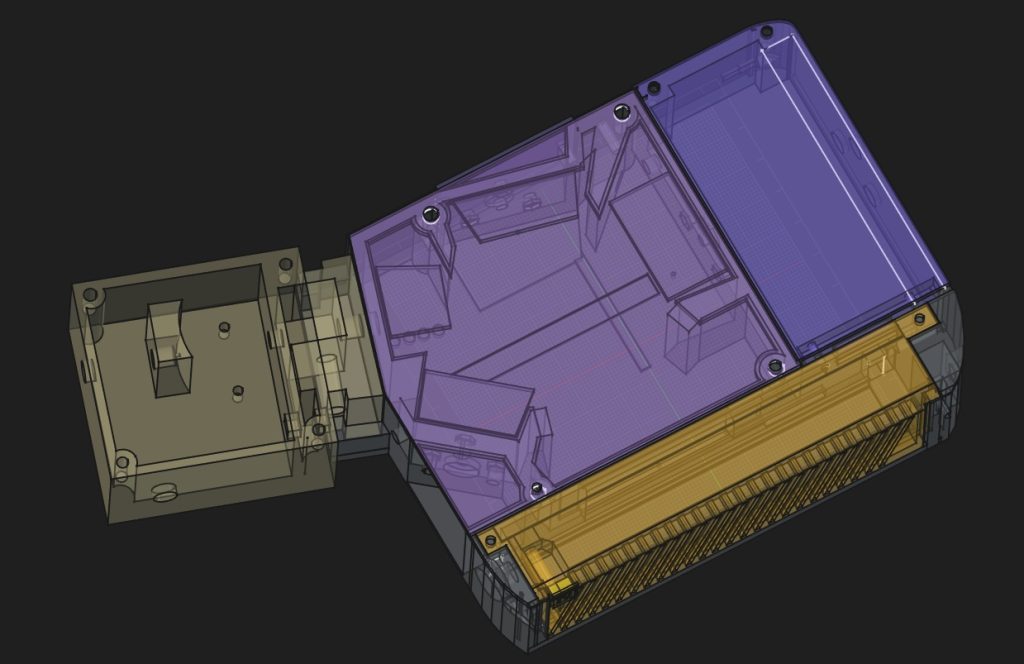
Bringing this UV-Vis spectrometer to life in FreeCAD has been a true journey of design, testing, and continuous refinement. So far, the project has spanned over six months (with a few breaks along the way) and devoured three full spools of filament.Currently, the entire chassis is 3D-printed from white PET-G, with the interior coated in a matte black finish. To ensure flawless performance, every single mating surface has been meticulously engineered to prevent any stray light from reaching the detector. For absolute light-tightness, critical areas inside the housing are lined with self-adhesive black flocking sheet (a velvet-like material). Below is a look at the current FreeCAD model, stripping away the electronics and optics to show the core structural design:
Results
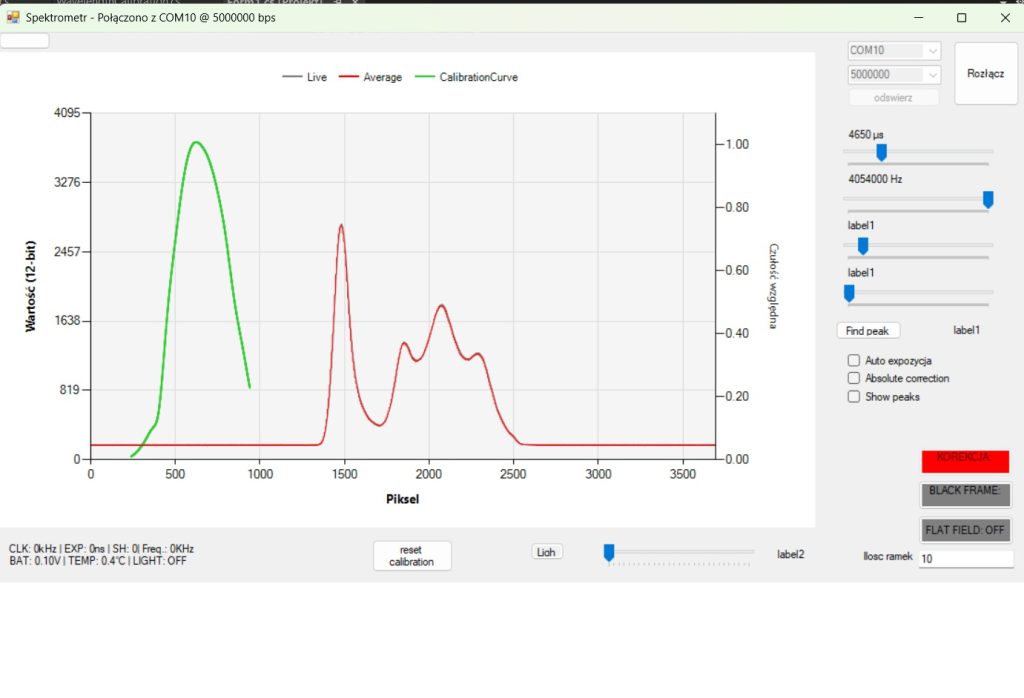
The red line represents the LED light at full speed. The green line is related to sensor sensitivity but it works only after callibration.
Stability and Noise Performance
One of the most important things in a spectrometer is how clean and stable the signal is. So let me show you what this system can actually do.
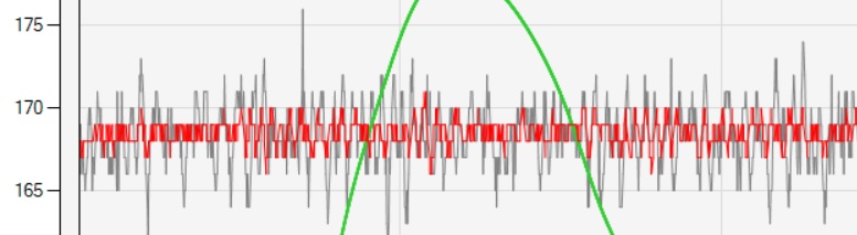
In the chart above, the grey line shows a single raw frame straight from the TCD1304DG sensor. The red line is the average of 10 frames.
As you can see, the raw frame has some visible noise — in the flat areas (away from the main peak) it swings roughly ±7 to ±8 counts. That translates to a standard deviation (σ) of about 2.5–2.7 counts. For a CCD running at 3.72 MHz, this is actually a very respectable noise floor.
But the real magic happens when we start averaging. After combining just 10 frames, the noise drops dramatically. The red line becomes much smoother, with deviations usually staying within ±1 count. When we push it to 32 frames, the line becomes almost perfectly flat — the remaining noise falls below 0.5 counts.
Position Stability – The Most Important Part
While low noise is nice, what really matters in spectroscopy is how stable the position of the spectral line is.
At 3.72 MHz I’m getting the following results:
- Single frame: σ ≈ 0.85 – 1.0 pixel
- 10 frames: σ ≈ 0.27 – 0.32 pixels
- 32+ frames: σ drops below 0.10 pixels
This means that after averaging around 50–100 frames, the position of the peak is stable to within ±0.2 pixels in most cases. In practice, the line barely moves at all — exactly what you want for precise measurements.
How Does This Compare?
In the world of amateur and DIY spectrometers based on the TCD1304, these results are genuinely strong. Many home-built systems show position jitter (σ) of 3 to 6+ pixels on a single frame, and often need heavy averaging to reach even 1-pixel stability.
This build performs noticeably better thanks to several key factors:
- Clean analog design with an ultra-low-noise LDO (LP5907), precise current sink (BC860C), and good buffering (AD8051)
- Solid star-grounding and careful PCB layout
- Optimized bare-metal timing on the Teensy 4.1
- Running at a well-chosen sweet-spot frequency of 3.72 MHz
All of this while still maintaining a comfortable real-time acquisition rate of around 30 frames per second.
All of this while still maintaining a comfortable ~30 frames per second acquisition rate.
Blue tooth
Previously, the system relied on an older HM-10 Bluetooth module, which proved to be a major bottleneck, bottlenecking data transfer speeds significantly. To solve this, the system now runs on a new ESP32-C3 co-processor, featuring a highly optimized transfer protocol and strict CRC frame validation in the code. Thanks to this upgrade, transmitting a complete spectrum along with all metadata now takes less than 1 second—at a range of up to 10 meters! However, to keep this specific code release as clean and streamlined as possible for USB communication, the ESP32-C3 firmware and its wireless libraries are excluded from this post (see the code above).
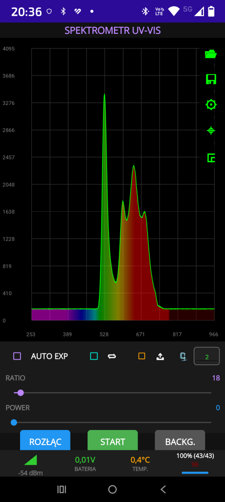
Full Ecosystem: Android Integration & Optical Precision
While the bare-metal code handles the raw data, the true power of this spectrometer is unleashed through a fully functional Android application. This mobile station transforms the Teensy-based sensor into a professional-grade laboratory tool.
Advanced Software Features:
- Absolute Spectral Correction: The app doesn’t just show raw counts; it applies absolute calibration to provide scientifically accurate spectral data.
- Professional Measurement Workflow: Integrated functions for Background Subtraction (Dark Frame) and Flat-Field Correction to eliminate sensor non-uniformity.
- Cloud Integration: Seamless data export directly to Google Drive for further analysis, along with the ability to load and compare multiple spectra in real-time.
- Bi-directional BT Communication: Full remote control over the spectrometer’s parameters (exposure, gain, triggers) via a robust custom protocol.
- 3 points calibration
Advanced Spectral Calibration
To achieve scientific-grade accuracy, the system implements a 3-point wavelength calibration mechanism. Unlike simple linear scaling, our software utilizes a 2nd-degree polynomial (quadratic function) to map pixel positions to nanometers.
- Quadratic Mapping: By using three reference points (e.g., from a calibration lamp), the algorithm calculates the coefficients of a parabola: lambda(p) = ap2 + bp + c p is the pixel index and lambda is the corresponding wavelength.
- Precision: This approach compensates for the inherent non-linearity of the optical path, ensuring that every peak across the entire UV-VIS range is exactly where it should be.
Dealing with Optical Artifacts: Etaloning
As seen in the provided image, the raw signal often exhibits a characteristic „wavy” pattern known as Etaloning (or fringing). This interference effect occurs within the detector’s cover glass or the CCD structure itself, especially in the NIR/UV regions. Our software is designed to recognize and compensate for these patterns, ensuring that the final output represents the true characteristics of the light source.
The Connectivity Roadmap: From HM-10 to ESP32
Currently, the device utilizes a rock-solid transmission algorithm optimized for HM-10 Bluetooth modules. This ensures stable data flow for the current version.
Note: The specific Bluetooth library is intentionally omitted from the current source code release, as the project is transitioning to a dedicated ESP32 co-processor. This move will significantly boost wireless bandwidth and allow for even higher frame rates.
Hardware Autonomy & Advanced Control Features
The project has evolved into a fully stand-alone device, capable of conducting field measurements without a permanent connection to a workstation.
Power Management & Portability
- Battery Powered: The system operates independently on a built-in battery, making it truly portable.
- Integrated Charging: Charging is handled via a standard USB port, allowing for easy power-ups from a laptop or power bank.
- Electronic Soft-Switch: The device features a professional power management circuit – it can be turned on and off via a dedicated soft-touch button („na puszcie”), ensuring clean power transitions.
Programmable Optical & Mechanical Control
Everything is integrated into the Teensy-based motherboard and can be controlled directly from the software:
- Calibration Light Sources: Support for calibration LEDs and a standard incandescent bulb (used for flat-fielding) is fully integrated. Both are software-controlled for automated measurement sequences.
- Motorized Slit Control: One of the most advanced features is the programmable slit width control. The motherboard includes a servo driver that allows the user to adjust the optical resolution of the spectrometer remotely via the application.
Join the Development
This project is continuously evolving. If you are a developer, researcher, or spectroscopy enthusiast interested in contributing to the code, hardware design, or the Android ecosystem, I invite you to get in touch. Let’s push the boundaries of DIY spectroscopy together!
The Next Step: Ergonomic Field Housing
To transition from a laboratory prototype to a field-ready instrument, we are currently designing a bespoke 3D-printed enclosure. The focus is on extreme portability and optical integrity:
Ruggedness: Designed to be printed in matte black ASA for thermal stability and superior stray-light absorption.
Light-tight Compartmentalization: Separate chambers for high-speed electronics and the sensitive TCD1304 optical path.
Field Ergonomics: A compact, rounded design featuring an integrated soft-touch power button and a protected USB charging port.
Smart Mechanics: The housing includes dedicated mounting points for the servo-controlled slit mechanism and internal baffles to eliminate stray light.
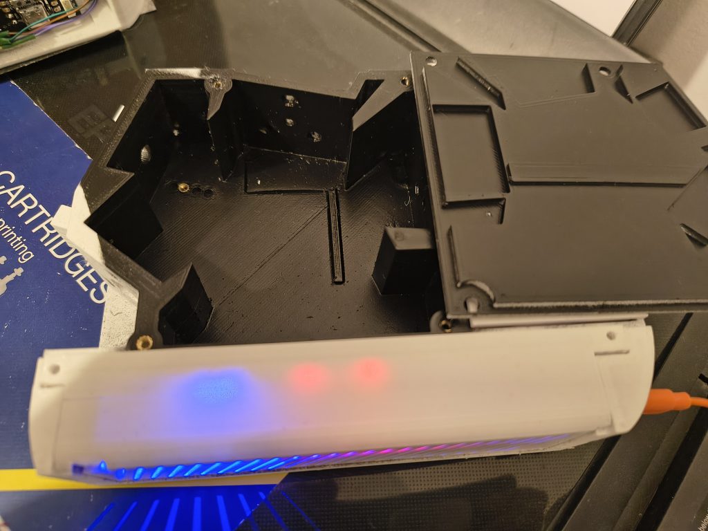
Here is a look at the latest iteration of the spectrometer (which is still evolving). On the electronics front, the hardware is now fully complete, with the PCB having reached its polished 6th revision. Here is a quick overview of the electronics driving the system. The power switch operates just like a smartphone: a simple click boots up the module, and another click shuts it down safely. This was achieved using a custom bistable (latching) electronic switch circuit.
The entire system features comprehensive battery management for two thick Li-ion cells (type 21700), chargeable via a standard USB-C cable or directly from a PC. To ensure future-proofing, the PCB already includes dedicated laser control outputs for upcoming Raman spectroscopy experiments. This upgrade will feature a 1200 lines/mm diffraction grating combined with dual, high-precision astronomical narrowband interference filters (specifically, laser line cleanup filters).
**Additionally, the board includes a control interface for the spectrometer’s light source. The lamp module itself utilizes a high-frequency converter and voltage stabilizer; however, this stage is still a work in progress while I wait for the unprotected mirrors.
**Naturally, the telemetry tracks both battery voltage and system temperature. On the signal conditioning side, the sensor output is adjusted via an operational amplifier (op-amp), while the detector itself is fully isolated using a dedicated current isolator.
Power delivery is handled by a combination of switching regulators and low-dropout (LDO) linear stabilizers. To maintain absolute signal integrity, I used decoupling inductors and completely separated the analog and digital power rails. The analog circuitry runs on 4.5V, while the digital logic operates at 3.3V. To minimize noise, the analog section uses a strict star-grounding technique (connected at a single point). When it comes to field readiness, the dual-cell battery setup delivers exceptional runtime, easily providing 2 to 3 hours of continuous measurements with the light source fully powered. As you can see, everything functions flawlessly! I will dive into a much deeper analysis of the electronics in a future post.

The latest addition is an automatic slit controller powered by a servo motor. It’s engineered for extreme precision.

The latest upgrade features an automated slit mechanism designed to deliver extreme precision. It utilizes a two-stage gear reduction system, with the motor operating at a resolution of 64 microsteps, though it can go as high as 256 microsteps. To ensure smooth operation and maintain adequate torque during these micro-steps, the motor is driven by a higher voltage—12V in this case. Best of all, the entire controller can be easily operated directly from a smartphone.
To do list
Next on my to-do list is custom mirror fabrication. Right now, commercial mirrors—especially the two used in the Czerny-Turner layout—suffer from severe etaloning, which ruins the accuracy of the readings. To eliminate this nightmare of spectroscopy, you need mirrors without any dielectric protective coatings. Most commercial options, like the ones from AliExpress, come pre-coated because they are tailored for astronomy, but that thin protective layer is detrimental to UV-Vis precision. To solve this, I purchased mirrors with an F75 focal curvature (heads up: on Ali, these are often listed as double mirrors with an F150 rating). They also need to be cut down to fit the device’s dimensions. In my case, I had to reduce the diameter from 50mm to 30mm—a task any local optician can handle, as it’s a standard procedure for cutting eyeglass lenses. The ultimate challenge, however, is vacuum-depositing a layer of pure, unprotected aluminum onto the glass. To achieve this, I built a custom vacuum chamber using a 3-clamp ISO system, machining a custom flange to hook it up to a professional vacuum setup (complete with a turbomolecular pump, precision gauges, etc.). Inside, I’ve installed a crucible Al2O3 with a tungsten wire mesh. While I haven’t tested the deposition process just yet—which will get its own dedicated blog post—I have high hopes. The chamber successfully pulls a vacuum well below the required 1 times 10^-5 mbar. Now, I’m just waiting on a few final pieces to complete the setup. In total such system costs ~50Euro.